Strange Problem with XLR Cables

peterjung

New member
Hi there – I have just signed up to this forum so hi everyone!


I was browsing the web looking for a solution to my problem when I stumbled across this forum – so I thought I would join up and see if anyone can help me out.


I have a pair of KRK Rokit 5 monitors. Until today I had these hooked up to an TC Electronics Desktop 6 Konnekt which worked fine. However the Firewire interface has become too problematic to make it work properly with Windows 10 so I recently bought an Audient iD6 with the USB C connection.


I previous was using two XLR cables each with a XLR to ¼ jack adapter to connect the monitors to the Konnekt 6.


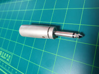
I need longer cables after rearranging the place so I bought a couple of 15m long cables which have an XLR male on one end and a ¼ jack on the other – thinking this would do away with the need for the XLR to ¼ adapters.


However, I get everything all set up nice with the iD4 but nothing from the monitors? The headphone out on the iD4 works fine. I tried the old XLR cables with the adapters and these work fine too.


Does anyone have any idea why these new cables will not work? Is there more to these cables than I am realizing? Here is the information on the cables I bought:

Image2.jpg

If anyone can help me out at all I would really appreciate it it!

Thanks and glad I found this forum - lots of great information on here!

Thanks in advance

Peterjung
 
Hi Peter and welcome. Those are the wrong cables. You need THREE pole jack plugs, often called "stereo" but more properly in this instance "Tip, Ring, Sleeve" and designed to carry a balanced* signal. Oddly, they SHOULD actually have worked but it would seem the AI has an odd output configuration? But even if they had worked you would still not get the noise bucking benefits of balanced operation. To add to your discomfort! Had you just bought XLR to XLR male to female cables to extend the incumbents it all would have worked fine! However, it is always a good plan to avoid audio adapters where ever possible.

* "Balanced" signal transmission is a mysterious matter to many and much misunderstood. I can give you a basic idea if you like.

Dave.
 
Hi Dave and many thanks for your reply.... I figured it was probably something along these lines and you have confirmed my fears.... :(

However, what is confusing me is that the XLR to 1/4 adapters I used before do not have the "tip, ring, sleeve arrangement" - only "tip and sleeve" see below.

Oh well, another lesson learned - everyday is indeed a school day!

Thanks again Dave - your reply is very much appreciated!

xlr.jpg
 
You are very welcome. There are two ways to wire an XLR 3 pin to 2 pin jack plug. XLR pin one always goes to sleeve (ground) and pin two almost always to tip but it is possible it is taken to pin 3. "Sod's Law. We get that A LOT in audio!

Dave.
 
You are very welcome. There are two ways to wire an XLR 3 pin to 2 pin jack plug. XLR pin one always goes to sleeve (ground) and pin two almost always to tip but it is possible it is taken to pin 3. "Sod's Law. We get that A LOT in audio!

Dave.
"Sod's Law. We get that A LOT in audio!"

ain't that the truth!!! :LOL::LOL:

Thanks again... :-)
 
If you can solder - you can fix them in a jiffy. Open up the XLR and swap pins number 2 and 3. Leave 1 alone. In the jack connector, either 2 or 3 will be connected to pin 1 (the screen. If the output you are driving them from has the opposite one shorted - then absolutely nothing happens.
 
If you can solder - you can fix them in a jiffy. Open up the XLR and swap pins number 2 and 3. Leave 1 alone. In the jack connector, either 2 or 3 will be connected to pin 1 (the screen. If the output you are driving them from has the opposite one shorted - then absolutely nothing happens.
Hi Rob - thanks for your input - I only just got a chance to have a look at this.

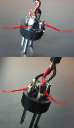
The cables I have seem to be wired a little differently:

1 - Shield and Ground
2 - Red
3 - Black

At the 1/4 end the jacks seems to a a molded case arrangement so I cannot open it to see the wires, however according to my old Fluke, both Red (Pin2) and Black (Pin3) are connected to the tip and the shield connected to the sleeve.

Image6.png

Image12.png

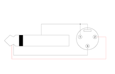
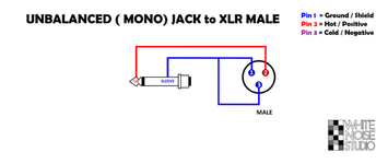
I found the following diagram online which is again different so I am somewhat confused??

Image10.png


So.... based on this would I be correct is assuming that the problem is at the 1/4 end rather than the XLR end? If I cut off the existing 1/4 jack and wire new ones as:

Connect Shield to 1/4 Sleeve
Connect Black to 1/4 Sleeve
Connect Red to 1/4 Tip

Would that work?

Thanks again!
 
Usually, to convert an XLR plug from Balanced-to-unbalanced, Pin 3 (Cold, or - phase) is connected to ground/sleeve, Pin 2 (Hot, or + phase) is connected to Tip, and Pin 1 (Ground) is connected to sleeve.
 
That’s frickin stupid. 1-1 = silence. Cut either of the wires going to the tip at the XLR end. Ideally it would be disconnected at the tip end, but it shouldn’t much matter. You can’t reconnect it to the shield from the XLR end, so you have to just leave it hanging in the wind and trust the shield to do its job. Unless you want to just hack those TS ends off and replace them.
 
XLR inputs are only really interested in the signal being between pins 2 and 3. connecting the tip to both produces no signal at all. the jack connection from the tip only is stupid.
 
Well, I posted this thread about two months ago... it was only today I actually got any time to look at this again. Hacked the 1/4" moulded jacks off, and with two new 1/4 jacks connected 1 & 3 to the sleeve and 2 to the tip... jobs a good 'un!

Sounds great!

Thanks for everyone who chipped in with some help :giggle:
 
Back
Top