evm1024
New member
OK - got it - Now we know how to do it
Sometimes it is hard for me to let go so I kept after the DX4 mod till I understand it now. Several people brought a part of the puzzle into focus for me. It helped me understand why tascam did it this way. Thanks!
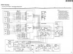
I only have a schematic and some parts were not making sense to me.
OK so here goes. THe DX4 (and presumed dx2 and dx8) do not switch states internally. Both encode and decode are functioning all the time. (except during power up)
The control connector is only to prevent the unit from being used on other than teac/tascam decks. THe deck provides +5 volts and ground to power the LED side of the opto-isolator and its driver circuit and a 1 Hz square wave to identify the deck as a tascam.
At first I thought there was something clever going on where the duty cycle of the square wave would also act as a signature but I don't think so now. THere is a electrolytic cap that blocks DC so you just cannot pull the signal pin to +5 or to ground and have it work.
The second area of confusion was the circuitry that controls muting of the input and outputs. The answer here (mostly) is that after power on the mute is active for a second or 2 to allow the circuits to become stable. No muting based on the state of the deck.
Then Herm told us about the channel LED not working if the unit is not plugged into a deck....Clink, the last part fits into place.
So the 1 Hz passes through the electrolytic, it goes to a half-wave rectidier and into an RC network which feeds the negative input of and opamp which drives the LED of the opto-isolator. The opamps output goes low which turns on the LED. The photo diode in the opto-isolator starts to conduct and pulls the base of transistor Q001 to near the same value as its collector (which is at ground). Q001 now conducts pulling its emitter to ground.
Q001's emitter is connected to both the channel LED cathodes through the channel enable switches as well as the muting circuit. When Q001 is conducting (a deck is connected and sending a 1 Hz signal) the channel LED will work (the switches bypass or route audio through the encoder/decoder regardless of the control signal) and the muting circuit is turned off thus allowing audio to pass through the encoders/decoders.
Now for the mod to allow the DX4D to work with any deck....
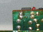
THe mod is simple. all one needs to do is to tie the base of Q001 to ground. Which causes Q001 to conduct. THe actual mode is quite easy. One only needs to solder a wire across pins 3 and 4 of the opto-isolator (this is also the base to ground of Q001). It can be achieved from the bottom of the unit.
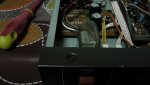
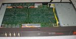
First pull off the bottom access panel after removing the 4 screws holding it in place. You did UNPLUG it from power didn't you?
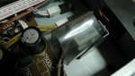
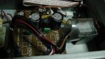
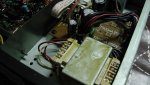
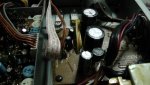
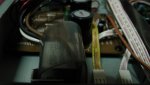
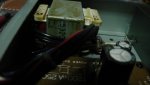
With the unit upside down and the front toward locate the Control PCB assemble. (circled in red in the photo)
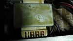
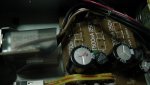
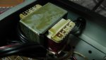
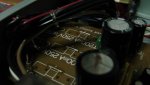
In the left corner of the control PCB you will find the opto-isolator IC. In the second photo you will see a jumper installed between pins 3 and 4. (Circled in red).
Just solder in a jumper like this and your DX4D will work on any deck (signal levels allowing).
Regards! Ethan
Sometimes it is hard for me to let go so I kept after the DX4 mod till I understand it now. Several people brought a part of the puzzle into focus for me. It helped me understand why tascam did it this way. Thanks!
I only have a schematic and some parts were not making sense to me.
OK so here goes. THe DX4 (and presumed dx2 and dx8) do not switch states internally. Both encode and decode are functioning all the time. (except during power up)
The control connector is only to prevent the unit from being used on other than teac/tascam decks. THe deck provides +5 volts and ground to power the LED side of the opto-isolator and its driver circuit and a 1 Hz square wave to identify the deck as a tascam.
At first I thought there was something clever going on where the duty cycle of the square wave would also act as a signature but I don't think so now. THere is a electrolytic cap that blocks DC so you just cannot pull the signal pin to +5 or to ground and have it work.
The second area of confusion was the circuitry that controls muting of the input and outputs. The answer here (mostly) is that after power on the mute is active for a second or 2 to allow the circuits to become stable. No muting based on the state of the deck.
Then Herm told us about the channel LED not working if the unit is not plugged into a deck....Clink, the last part fits into place.
So the 1 Hz passes through the electrolytic, it goes to a half-wave rectidier and into an RC network which feeds the negative input of and opamp which drives the LED of the opto-isolator. The opamps output goes low which turns on the LED. The photo diode in the opto-isolator starts to conduct and pulls the base of transistor Q001 to near the same value as its collector (which is at ground). Q001 now conducts pulling its emitter to ground.
Q001's emitter is connected to both the channel LED cathodes through the channel enable switches as well as the muting circuit. When Q001 is conducting (a deck is connected and sending a 1 Hz signal) the channel LED will work (the switches bypass or route audio through the encoder/decoder regardless of the control signal) and the muting circuit is turned off thus allowing audio to pass through the encoders/decoders.
Now for the mod to allow the DX4D to work with any deck....
THe mod is simple. all one needs to do is to tie the base of Q001 to ground. Which causes Q001 to conduct. THe actual mode is quite easy. One only needs to solder a wire across pins 3 and 4 of the opto-isolator (this is also the base to ground of Q001). It can be achieved from the bottom of the unit.
First pull off the bottom access panel after removing the 4 screws holding it in place. You did UNPLUG it from power didn't you?
With the unit upside down and the front toward locate the Control PCB assemble. (circled in red in the photo)
In the left corner of the control PCB you will find the opto-isolator IC. In the second photo you will see a jumper installed between pins 3 and 4. (Circled in red).
Just solder in a jumper like this and your DX4D will work on any deck (signal levels allowing).
Regards! Ethan
 Now I'm curious to open mine to see if it's been modded. It works anyway but If I do this I let you know. That may be the difference I was confused about between the two I had. One I bought from Herm and sold to Sweetbeats. It works fine but I don't think it lights up until you plug it in to the deck. You might want to mod it sweetbeats. It's good to know that you can use them with anything.