K
Killer B
New member
Hi Everyone.
Im just brushing up on the ol' phantom power, Its just a simple question.
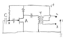
If Phantom is 48v across pins 2(+ve) and 3(-ve), then if I have to use an unbalanced cable that grounds pin 3, its still going to supply phantom power to the mic, eh?
I'd try it out, but first I want to know if there are any dangers in it! And also, has anyone noticed any nasty noise or interference as a result?
Thanks.
-A
Im just brushing up on the ol' phantom power, Its just a simple question.
If Phantom is 48v across pins 2(+ve) and 3(-ve), then if I have to use an unbalanced cable that grounds pin 3, its still going to supply phantom power to the mic, eh?
I'd try it out, but first I want to know if there are any dangers in it! And also, has anyone noticed any nasty noise or interference as a result?
Thanks.
-A
")