Parametric EQ build

Good luck
I've never done this myself although i have a book with a project to build, i ordered the parts but never got round to it!:facepalm:
but i will say i used to sing/play in a band once where the lead gtrist said i'll build the PA & i thought yeh:laughings:

was i ever wrong he built the amp from a kit which was superb, but to this day i've never used a better mixer(for live work)

it would've been great to try it recording but we didn't, but i'll watch how you get on with interest :guitar:
 
Looks intresting. You can bet if R G Keen designed it it will be effective.
Do let us know how the build goes and how it turns out and what application you will be using it for.
I'll be back to check how you got on
Rich
 
Okay,
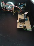
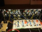
after a very long mission to get the chassis drilled, it's been done! So I've started constructing the unit. I've finished the power supply and have started soldering the main board. Hopefully it'll be finished in the next few days.
1233359_725528517461043_98806823_n.jpg
 
Does the power supply eventually get enclosed, both for safety and also to protect against hum and noise getting into the main circuits?
 
I can't see if there are caps across the regulator outputs and 0V.

If not, check the data sheet for the devices used, as you probably need something like 0.1uF across the output rail and 0V.

I would also suggest using heat shrink tube to insulate the active mains where it is soldered to the fuse connector. Extra safety.

Final tip... where enclosure panels join together, grind away a bit of paint (or whatever finish), because this ensures good conductivity to ground through the enclosure. Doesn't have to be everywhere - perhaps a couple of corners. This increases safety and (I think) shielding.

Just my 2c worth...

Paul
 
Does the power supply eventually get enclosed, both for safety and also to protect against hum and noise getting into the main circuits?

I have little knowledge but I was gona ask the same thing.
I ended up pulling the transformer out of a build and housing it externally because I couldn't get around the buzz.

I do have others where it's not a problem though.
 
Does the power supply eventually get enclosed, both for safety and also to protect against hum and noise getting into the main circuits?

Indeed! Do get some heat shrink sleeving for that fuseholder and any other exposed mains connections. One day you WILL brush against it and the whole lot will end up on the floor, probably broken!

+1 also about the regulators. 10microfarads close to both input and output and since they are cheaper than chips, a 1N4007 or similar across the reg device will help protect it.

I also like to hang a LED to PSU rails. Buy a lucky bag of 'em.

I commend to you Douglas Self's book: Small Signal Amplifiers. A veritable treasure trove of information and circuits for quality audio gear. INCLUDING the right way to use 78/9xx regulators!

Dave (oops! Sorry, din't see the heatshrink mench') Me again! James. Just noticed you are UK? I have a house full of electronic "junk". Please feel free to PM and ask. If I have it, yours for free.
 
OT heatshrink aside...

I bought a bunch of different sizes a few months ago, used a few inches of one size to fix a radio mic transmitter antenna for my son's school, then put the lot away. Since then I've not been able to find it.

1. Yes, senility is setting in.

2. If we have any psychics on the board, HELP!

Dunno about a psychic Bobbs. I think you need to see a shrink!

Dave.
 
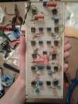
Okay, here's the main board:

1239973_726703650676863_1708327267_n.jpg

I'm hoping to get it finished tomorrow. The only problem is that the front panel might need another coat of paint. I've given it four so far and it's still a bit streaky :/

The whole thing will be enclosed so there's no chance of touching that live terminal. I've put the 10uF caps on the main board rather than the power supply board. I'll solder in those diodes too if that protects the regulators.

ecc83: thanks for the offer! I'm already swimming in 'junk' here though so I'll have to give it a miss. Thanks again for offering though.

Thanks for all the comments guys! It's nice to have interest and suggestions :)
 
" I've put the 10uF caps on the main board rather than the power supply board."
Ah! If they are not within 10mm or so of the regs they will not perform their intended purpose very well which is noise reduction so if you don't have a noise problem, no worries.

The diodes protect the regs from the discharge of large caps on their output, does not look as tho' you have any?

Dave.
 
I'd still put a 0.1uF (suitable voltage) across the input and output of the regulars, physically close to the regulator devices - just because it is in the data sheets :D

I think, though, that these caps help with regulator stability and transient response.

Your chosen op-amps may also need local de-coupling - looks like you've done that?

Paul
+1.
Re the ICs I often just solder the 100nF across the copper side of the board, keeps the wires really short.

Dave.
 
Okay,
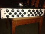
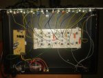
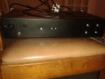
I've finished building it now. I tried the unit without the big capacitors on the outputs of the voltage regulators and there was no noise so I left them out. I didn't want to risk messing up the board. Yep, I've got ceramic decoupling caps on all the op amps.

The unit works almost perfectly apart from a couple of problems. One of the bands is dodgy (I'll go over all the connections, I imagine one is loose) and also there's a bit of crosstalk between the channels. When both channels are engaged, some of the signal from channel 1 is available at the output of channel 2 and vice versa. What could be the problem here?

577901_728001233880438_1885659181_n.jpg1185124_728001340547094_931464516_n.jpg1234506_728001377213757_1888074083_n.jpg1238096_728001253880436_915252376_n.jpg
 
There's no transformer hum that I can detect, the whole thing is really quiet. The only problem is the crosstalk :/
 
Sorry this is a little late in reply to the OP but...

Yes! I am currently working on a multi-effect project with Keen's Para eq design incorporated. I'm only using a single band though. I felt the original frequency sweep was not broad or deep enough as I intend the eq to be more for live sound manipulation as well as a static tone control. I changed some component values to get a more intense frequency sweep. For 7 components, 3 pots and an opamp I think it's simply the easiest, best para eq circuit.
 
Back
Top