Yup. only 2 prongs. i have some outboard gear and cassette multitrack tapes, and also hybrid setup to PC, it's all connected and i never had noise problems..but maybe it's time to do something about it.
I would say in the sense that you’ve never had an issue with noise problems then
no don’t start fixing something that isn’t broken. More below.
does it have to do something with the way i will choose to wire the cables?
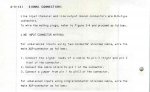
No it really doesn’t. Even if you find you have “noise problems” (and there are a couple different categories of noise problems...more below), you’re not likely to wire the cables differently, unless you find you are having to make sweeping changes to the grounding of multiple devices to address a problem. That’s the key...I wouldn’t go down the rabbit hole at all unless you are having “noise” issues. Assuming your M-512 is hub if your studio, if you are having noise issues with the cables to/from the tape machine, I would start by disconnecting the wires from pins 1 & 2 of the XLRs at the tape machine. But ONLY if you are have issues you otherwise can’t resolve.
I have learned that the best way is to ground only the mixer and keep all the rest "floating", grounded thru the mixer, is it true to your knowledge?
I can’t generally agree with that methodology. And we need to define what you mean by “ground” the mixer. Do you mean connecting the chassis of the mixer to the building ground (through a 3-prong grounded power cable, and this is also assuming the grounded power outlet actually has the ground conductor wired back to the service panel and the ground buss is actually appropriately bonded to a ground rod that is in...the ground)? If that’s what you mean, understand the 3-prong power cable does not directly *necessarily* have anything to do with your audio signal ground...it *may*, but it depends on the problem present, your equipment specifics, etc.
When we talk about grounding in electronic audio equipment, there two camps to address: the safety ground, and the audio signal 0 volt or “ground” reference (as well as any other systems within a particular piece of gear, like logic circuitry, lamps, etc). The ground prong is a “safety ground.” It is there to protect you in the event there is a failure in the device, building wiring or electrical service involving the neutral leg of the AC power source. Without the safety ground the hot leg of the electrical service is then going to try to resolve this failure through you and any physical continuity you have to physical earth. With a safety ground in place, that becomes the pathway to resolving the neutral leg failure. So the fact your console does not have a 3-prong power cable, just means it does not have a safety ground bonding the chassis to literal earth. So there’s the safety consideration, but also the potential for unwanted noise (60 or 120Hz hum typically) if you have multiple devices with no common earth reference, or in the absence of earth reference no common bonding of each chassis’ ground reference to each other. The best way I know to eradicate this problem is to, if possible, have all devices plug into a single circuit (be on one breaker), and for each device to have its chassis bonded to the ground conductor of that circuit either through a 3-prong plug (and for the ground conductor of that plug to be positively bonded to the device’s chassis as close as possible or to the entry point of the cable into the chassis), or for a device with a 2-prong plug to have its chassis bonded to the building ground (through a separate cable bonded to the device’s chassis and then terminate at building ground...this is preferred), or if that is not possible for the device’s chassis to be bonded to the chassis of another device that *does* have a proper bond to building ground through a 3-prong plug. The goal is for each device to have a path to ground (for safety), and for each device to have only one path to that ground. This avoids loops and differentials that increase the risk of line service hum.
So now that we’ve addressed safety and common chassis earth reference for each device, we have to go next to the complicated part; how each device’s internal ground scheme is designed. If all devices’ ground scheme topology was the same, we’d be done. But there’s no standard. There or some common practices, but if you have multiple devices from multiple manufacturers and multiple eras, you are highly likely to find differences, and/or bad designs. So then if you have problems with noise at this level (usually manifesting as higher than spec noise floor or RF noise induced into the audio path), to fix the problem you have to pull out the schematics and open up each device to find out how they did it and modify things so there is some commonality between all your devices, and possibly fix bad designs. I had to do this with my Soundtracs MX series console I used to have. And guess what? There remains controversy around what is the “right” way or what is the best practice implementation for signal grounding. It is a topic of ongoing debate. My practice is to ensure that the shield/signal ground/“pin1” of each audio input/output jack is bonded to the chassis as close as possible to where the jack is located, that the 0 volt or “ground” reference for each audio power rail is bonded to the chassis as close as possible to the output of the power supply, that all metal parts of the chassis are positively bonded to each other, and that the signal ground plane of each active audio circuit (whether it’s on a PCB or point-to-point wired, or something in between) connects to the chassis at only one point for each circuit or board.
So...
You see...
It is not simple. So I recommend, leaving it alone unless you are having problems.
I was without knowledge in this area when I owned an M-520...but I never had problems either. I had gained knowledge when I had an M-512, but didn’t look closely at any of this. I *have* looked closely at this with my early 80s Tascam prototype console (the Tascam “M-__”), which was a prototype for the M-50/M-500 series, and I’m using a modified PS-520 to power it. Part of the modifications to the power supply include changes to the ground scheme. I also revised the bonding between the power supply chassis and console frame, as well as the bonding of all the supply rail 0 volt references to the console frame. These changes would all likely carry over in some way to the M-520. I’m not sure about the M-512, but some of these issues would be essentially irrelevant to the M-512 since it has an onboard power supply. In my prototype console there are some minor improvements I could make to the individual grounding circuits in the console to maybe improve RF rejection, but it’s not been an issue where I’m living, so I’ve left it alone for now. The Soundtracs MX was a different story, as I was living a block away from the highest power AM radio station in my state at the time, and the Soundtracs ground scheme on all points needed significant help.


")
")