timkroeger
Custom Title User
Hey there,
I have these nice pieces of gear:
The console's tape ins and d.outs are -10 dBV (TS). The tape recorders line input and output connections are 3-pin XLR +4 dBm. Some quotes from the manual first:
No mention of accomodating unbalanced inputs, yet.
Does the maximum source impedance or minimum load impedance change, if I connect unbalanced sources/destinations?
The following Figure 7-36 shows two XLR connectors for Input Connector Wiring. One for balanced, the other for unbalanced with Pin 1 (GND) and Pin 2 (Cold) short-circuited. So I think I can use an unbalanced input source, too.
Now, I calibrated the input amplifiers and meters using a +4dBu 1kHz testtone, configuring the amplifiers to read +4dBu at the output and the meters to show 0dB at that level. A few questions:
Look at the attached picture of block and amplifier diagrams below. It seems that internally everything is "amplified" to -10dBV just after the input and just before the output it's amplified back from -10dBV back to +4dBm (+2dBV). I am reluctant to use line level converters to mess with the signal since they are both expensive and introduce more gain stages. I'm also reluctant to tap into the circuits and fabricate some kind of break out cables... The questions are:
I could live with a "hotter" output from the tape machine but what can I do to reach the tape VU's 0dB? I think I could post additional pictures of the actual circuitry involved but I don't have a scanner right now so it would be pictures taken with my camera. Oh, thanks for reading")
Cheers
Tim
I have these nice pieces of gear:
The console's tape ins and d.outs are -10 dBV (TS). The tape recorders line input and output connections are 3-pin XLR +4 dBm. Some quotes from the manual first:
ATR-60/16 manual page 1-6 said:Standard 3-pin XLR-type connectors as well as 25-pin D-sub connectors make it easy to connect cables from INPUT and OUTPUT to the sound system. These transformerless balanced XLR-type connectors are specified as follows: Input impedance: 10 k ohms, nominal input level:+4 dBm (1.23 V), output impedance: 20 ohms, nominal output level: +4 dBm (1.23 V).
ATR-60/16 manual page 3-2 said:XLR-type Input/Output Connectors (Balanced): Pin 1 is GND (Shield), Pin 2 is Cold (Low) and Pin 3 is Hot (High).
Note: Short circuiting between Pin 1 (GND) and Pin 2 (Cold) will change the ATR-60-16's Output to accomodate unbalanced cables.
No mention of accomodating unbalanced inputs, yet.
ATR-60/16 manual page 4-6 said:Input impedance is 10 k ohms (balanced), input level is +4 dBm (1.23 V), and maximum source impedance is 600 ohms.
Output level is +4 dBm (1.23 V). Minimum load impedance is 200 ohms (balanced)
Does the maximum source impedance or minimum load impedance change, if I connect unbalanced sources/destinations?
ATR-60/16 manual page 7-23 said:Nominal input/output level is +4 dBm (1.23 V) and nominal output load impedance is 600 ohms, regardless of the type of connectors (XLR or D-SUB).
Output level is always +4dBm even if the XLR type connector's Pin 1 (GND) and Pin 2 (Cold) are short-circuited to change the ATR-60-16's output to accomodate unbalanced cables.
The following Figure 7-36 shows two XLR connectors for Input Connector Wiring. One for balanced, the other for unbalanced with Pin 1 (GND) and Pin 2 (Cold) short-circuited. So I think I can use an unbalanced input source, too.
Now, I calibrated the input amplifiers and meters using a +4dBu 1kHz testtone, configuring the amplifiers to read +4dBu at the output and the meters to show 0dB at that level. A few questions:
- Do I need to fool around with a 600 ohms resistor on the input for a 1.23V +4dBm signal?
- Was using another scale (+4dBu instead of +4dBm) wrong in this setup?
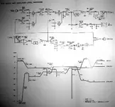
Look at the attached picture of block and amplifier diagrams below. It seems that internally everything is "amplified" to -10dBV just after the input and just before the output it's amplified back from -10dBV back to +4dBm (+2dBV). I am reluctant to use line level converters to mess with the signal since they are both expensive and introduce more gain stages. I'm also reluctant to tap into the circuits and fabricate some kind of break out cables... The questions are:
- What else can I do?
- What signals can I expect on an output that is short-circuited to unbalanced?
- What unbalanced signal level do I need to provide to the tape's inputs in order to reach 0dB on the VU meters?
I could live with a "hotter" output from the tape machine but what can I do to reach the tape VU's 0dB? I think I could post additional pictures of the actual circuitry involved but I don't have a scanner right now so it would be pictures taken with my camera. Oh, thanks for reading
Cheers
Tim
")

 Can't stop chuckling...
 :rolleyes:")
