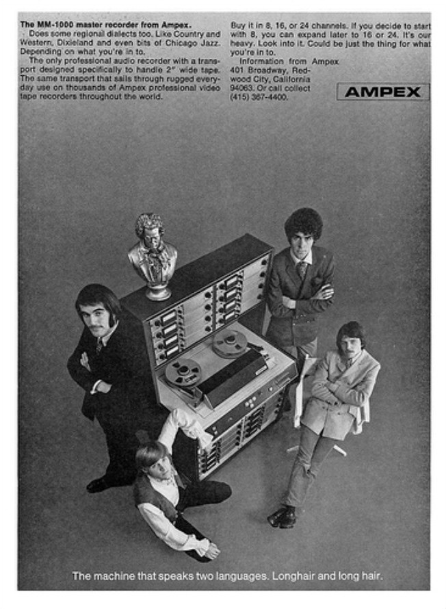
Ampex MM-1000 Story...

Nice video, Cory!

The fan noise in yours sounds about the same as the fan noise on my MS-16, though my transport is definitely quieter.

I guess in a very real sense, these machines were meant to be either in a machine room on their own, or at minimum, in a 2 room studio where it's away from the talent and any sensitive live microphones.

Good luck with the lifters! I'm sure you'll figure it out! ;)

Cheers! :)
 
lifters are working...

I wish I could say why...but I'm not concerned about it...

The troubleshooting effort gave me impetus to study, really study all of the schematics that pertain to the transport itself which is about 5 sheets worth. Now it has finally sunk in...the labeling and nomenclature conventions and which schematic to pull to see whatever I need to see in a certain situation...I'm as comfortable with the MM-1000 schematics as I am with a set of Tascam schematics now which makes the Ampex less intimidating.

So I was able to understand how and when voltage is present at the lifter solenoid and test it all out and everything was pointing to the solenoid being dead. After all the dickering I hooked the solenoid up one more time and *chuck-chuck*...bad internal connection? Something stuck inside? Dunno. Probably not the last time I'll have lifter issues but I'll save the dissection of the solenoid for the next bout. For now its time to focus on setting the brake, pinch roller and tape tensions.

BTW it appears to me that the capstan IS supposed to run even if tape is unloaded. I was told by a friend that theirs shuts off when that left tension arm goes to the park position (and opens the safety switch), but as far as I can tell in my schematics as long as the mains switch is closed (the breaker on the MM is 'on') the capstan is going to turn at 7.5ips...then once the safety switch is closed (tape is loaded) the speed switching relay can work in the capstan allowing 15ips. The safety switch provides ground for the 24V rail so nothing that operates on the 24V will work until the safety switch is closed...so all the relays and such, *but the capstan is powered straight off the 120VAC mains*. My friend's MM-1000 has the SERVO capstan which runs on 24VDC! So logically his *would* shut off with the safety switch open.

So everything is functioning now on the transport and its time to get the mechanical side of it dialed in and then on to testing the record and repro functions.
 
Speaking of the concerns for ambient noise-----

I tried visiting torridheatstudios.com, but is your page still under construction? I don't really know what your studio floorplan is like. Do you have a machine room, or you plan on making do with having Matilda in the same room as the mixer?
 
My "studio" is the epitome of dysfunctional...1400 sq. ft. house with a tight garage and 6 of us here...no recording room really and the control "room" is a 6' x 8' temporary structure in the garage. That's it. Doing overdubs here next week...guitarist will be out in the shop (full of hay and lumber), 1 vocalist will be in my minivan, and the other vocalist will be in the control "room"...I'll be remoting the DAW over WiFi with a laptop.
 
1968%20ad.jpg


Ampex%20MM-1000%201969%20ad.jpg
 
Last edited:
My "studio" is the epitome of dysfunctional...1400 sq. ft. house with a tight garage and 6 of us here...no recording room really and the control "room" is a 6' x 8' temporary structure in the garage. That's it. Doing overdubs here next week...guitarist will be out in the shop (full of hay and lumber), 1 vocalist will be in my minivan, and the other vocalist will be in the control "room"...I'll be remoting the DAW over WiFi with a laptop.

Dysfunctional? Sounds perfectly functional to me :D
 
Frustrating night...

GRRRR! Thought I was getting a good start on getting the transport adjusted...I started working on setting the brakes up tonight...I didn't get very far before I started feeling some nipping on a finger that was touching a tension arm post...out comes the voltmeter.

I've got 32VAC pumping through the transport plate and everything attached to it when referenced to the 24VDC supply chassis ground...if I pull the output cable of the 24VDC supply (which also carries 117VAC) the transport plate is dead (good dead)...so I've got to chase that down. And what I DID do on the brakes was fruitless...

Supposed to have 4.5lbs tension CCW on the supply side and I've got less than 0.5lb and the "high" adjust nuts don't do anything...the brake works fine but the scale tells me its WAY off and to make matters worse *I can't understand how the silly things work!* I have to get the mechanical logic into my head.

Enough for tonight. I'd normally keep at it until I've got it but I'm learning moderation...I'll have a fresh mind next time I approach. First step though is to figure out why the transport plate is hot. :eek::mad:
 
Take time with it (echo ech ec e ....)

Cory,

Try not to fry yourself or short the floating voltage to ground and fry something else.

Try to find out 2 things. The first is why any voltage on the tension are is not shunted to ground in the first place. You would think that it would be so as to prevent killing someone. And Second, where the stray voltage is coming form. Frayed wire in a harness or whatnot.

--Ethan
 
Its clear that it is just the transport plate and all the components that are attached to it that are hot...the plate sits in a tray formed by the top of the console, and since the console is painted with a heavy coat of paint the charge is contained to the transport plate assembly itself.

Man this is wierd.

I know that if I disconnect the transport plate assembly from power (which is conveniently on a single heavy-duty Amphenol connector) the transport is dead (no stray charge). I measured AC voltage on two of the pins on the main harness connector, and they both trace back to the mains supply, one neutral, one hot. Problem is that both measure positive AC voltage when referenced to the mains neutral... :eek:

AND...the voltage is present even when the main throw on the console is "OFF".

  1. Mains supply comes in through the mains plug at the back of the console and then goes directly to the breaker switch which breaks the hot line.
  2. From there the mains power goes to the cooling fan(s), the 39V supplies for the electronics, and the 24V supply.
  3. Mains power goes through the 24V supply and continues to the control relay box and up to the transport plate assembly (the capstan and reel motors are all powered straight off the mains).

Again, when the main throw is "OFF", there should be nothing anywhere but I am still getting voltage.

So, knowing that the charge was getting to the transport plate I figured to start disconnecting things on the transport plate one-by-one to see which one might be a "Trojan Horse"...every time I remove a component from the equation the voltage increases whether the main throw is "ON" or "OFF"!!! :eek::eek::eek::mad:

Here is what I measured with an AC voltmeter between the transport plate and the AC neutral leg (on the control relay box at J1 pin 5...this is where the mains voltage comes IN to the control relay box after coming through the 24V supply:

  1. With everything connected and main throw "OFF" 6VAC
  2. Same as #1 but main throw "ON" 30VAC
  3. Now I disconnect the capstan motor, main throw "OFF" 9VAC
  4. Same as #3 but main throw "ON" 44VAC
  5. Now I additionally disconnect the takeup motor, main throw "OFF" still 9VAC
  6. Same as #5 but main throw "ON" still 44VAC
  7. Now I additionally disconnect the supply motor, main throw "OFF" 18VAC
  8. Same as #7 but main throw "ON" 86VAC
  9. Now I additionally disconnect the capstan dummy plug, main throw "OFF" 25VAC
  10. Same as #9 but main throw "ON" 68VAC

So, I've got some ideas but if anything sounds whacky with what I was doing above, let me know.

  • The mains cable I have for MM-1000 is an original cable but with an aftermarket plug at the wall receptacle end. It is not on there really good...maybe some kind of leakage between the hot and neutral? It is on my list to get a heavier duty plug and replace that but sometime tonight I'm going to check for continuity between the 3 conductors on that cable.
  • The MM-1000 is (if you all recall) in a temporary space while I finish going through it...it is plugged into a 15A power strip that is connected to a wall outlet, but I think the wall outlet may not be properly grounded. I'm going to check that...that could be bad yes?
  • There is also a small forced air utility heater connected to the same power strip. I noticed that when it kicks on the AC voltage measured at the transport drops from approximately 120VAC to about 75VAC, though everything still seems to run okay but I know the heater is on because the PSU cooling fan rpm drops noticeably (and remember that fan is powered directly after the breaker switch)...that sounds kind of wrong, yes?
  • Don't worry...I'm not directly touching anything on the MM-1000 while it is connected to the mains...there is always a probe or some other means of insulating me from it until this gets figured out. And no kids are near because I tinker after they go to bed...its in their playrooom after all. :o

And BTW, I understand how the brakes physically work now...the mental recess was good. I got them adjusted up just fine except for the "high" adjustment at the supply motor (the feeding direction or counter-clockwise rotational braking). Remember that's the brake with the pad that had fallen off the band. The braking force is supposed to be 4.5lbs when using 1" tape (7.5lbs with 2" tape) when measured with a spring guage strapped around an NAB reel hub. I still have room for adjustment but the adjustment nuts are much tighter at present on the supply side than on the takeup side, which I was easily able to adjust up to 4lbs. So maybe the pad is worn (who knows what caused it to fall off in the first place), maybe it is glazed even though it looked okay, or maybe it needs to break-in since it has been reinstalled on the band. I'm leaving it at 3lbs for now. I'll run things for awhile and check it periodically. It was set at about 1lb before (after reassembly) and things were working okay so I'm not too worried about it.
 
You need to check the protective grounds. There should be no voltages when the breakers are open. The chassis and any metal that humans touch should be grounded to the protective grounds.

Is this a single phase, 3 phase or split phase machine? Not that it matters too much the switch should open any hot mains line and the protective ground should shunt any faulty voltages to ground.

--Ethan
 
The Ampex mains cable checked out fine...no improper continuity between the three conductors.

The ground is absent on the wall receptacle I was using so I've got an extension cord to a filtered dedicated 20A circuit that I know is grounded and the power distribution unit verifies.

All the motors are single phase, Ethan.

I'm going to see if those stray voltages measured when the main throw was OFF were maybe related to charged system components (there are some HUGE capacitors in this thing...)

Its been unplugged for a day or so now so later I'll plug everything in, leave the main throw off and see if there are any stray voltages.

Ugh...I'm sure I'm going to find the problem in the control box which is bad because everything is hard-wired in there...Hard to isolate and troubleshoot...
 
Its madness...

Utter...freaking...madness.

Okay...the internal 3-conductor cable from the mains socket on the MM-1000 goes straight to the breaker panel...Ground goes to the metal panel, neutral goes to the buss bar, and hot goes to the breaker. The other side of the breaker connects to the buss bar. The buss bar has 8 pairs of screw terminals, and each pair is isolated from the others. I have verified that. I disconnected ALL THE OUTPUTS FROM THE BUSS BAR; FROM THE BREAKER PANEL. So *in theory* I've got hot and neutral coming into the machine but going nowhere. I even disconnected everything from the power supplies and the control box. Get this...I put one probe on the transport plate and I get 5~6VAC **without the other probe touching anything**! :eek: What th'....Then if I touch the other probe to the incoming neutral line I get about 33VAC...if I touch it to the incoming hot line I get about 78VAC.

I don't expect anybody is going to be able to solve this...but if you DO have some ideas/info/suggestions, oh my let me know.
 
Question

Utter...freaking...madness.

Okay...the internal 3-conductor cable from the mains socket on the MM-1000 goes straight to the breaker panel...Ground goes to the metal panel, neutral goes to the buss bar, and hot goes to the breaker. The other side of the breaker connects to the buss bar. The buss bar has 8 pairs of screw terminals, and each pair is isolated from the others. I have verified that. I disconnected ALL THE OUTPUTS FROM THE BUSS BAR; FROM THE BREAKER PANEL. So *in theory* I've got hot and neutral coming into the machine but going nowhere. I even disconnected everything from the power supplies and the control box. Get this...I put one probe on the transport plate and I get 5~6VAC **without the other probe touching anything**! :eek: What th'....Then if I touch the other probe to the incoming neutral line I get about 33VAC...if I touch it to the incoming hot line I get about 78VAC.

I don't expect anybody is going to be able to solve this...but if you DO have some ideas/info/suggestions, oh my let me know.

What country are you in ? :) I know your profile says Pacific Northwest, but you usually don't hear Americans say "mains."

I'm not entirely clear on your set-up here. I assume single phase power in a household environment - 120 or 240 VAC? Is it a single voltage or dual (120/240) outlet?

Have you checked the outlet with nothing plugged to make sure you don't have a ground fault? You should check, as this can be deadly.

Also assume the meter is set to measure AC Volts.

The single probe reading is just noise. Don't worry about that.

Are there two bus bars, one for neutral, one for hot?

Do you have schematics?
 
jviss, thanks so much for the reply.

Yes I'm in the U.S...'Mains' is just terminology I've assimilated since it seems to often be the reference term used in a lot of my manuals...plus I just like it.

So, yes, single voltage 120V domestic supply...the machine WAS connected to a non-grounded outlet but I switched to a dedicated filtered verifiably healthy ground circuit (see a couple posts ago)

Meter set to AC, check!

5~6VAC 'noise'...I guess that would be possible...bunch of big flourescent shop lights in the room and a radio station down the street...

I guess 'buss bar' isn't the right term...there is an 8 x 2 screw-terminal block...8 sets of paired terminals that are isolated from each other.

I've got the foll service manual including schematics...shall I post a link??
 
Here are the schematics: https://www.torridheatstudios.com/documents/Ampex/Ampex%20MM-1000/Ampex%20MM-1000%20Schematics%20(September%201969,%204890304).pdf

This is driving me batty...I checked for continuity everywhere to verify that voltage would be able to stray (in order to make headway on isolating where it is getting through), but I can't find any continuity anywhere, and yet when I turn it on the transport plate is charged.

There is no possible way that I have physically observed, determined from the schematics or measured that voltage could stray to the transport plate, and yet flip the switch and there it is. :mad:

Everything is disconnected, folks...the harness is disconnected from the transport plate, all the regulated power supplies, the relay box...power should go...nowhere, and the continuity tester confirms.
 
Last edited:
Don't try this, but...

...way back when, when we suspected a short that we couldn't find in a system, we'd connect a high-current power supply and burn it out! Sometimes we'd shut off the lights and get a bunch of guys, all assigned to watch a certain part of the system as the power was applied: watching for a glow, or spark.

You might have a short somewhere in here. Is there any reason t think so? (I haven't been following the saga).
 
It's entirely possible that some of the solder joints in the vicinity of the power supply were either faulty, or lead-free, and have a symptom called Tin Whiskers: http://reason.com/blog/2009/07/07/did-banning-lead-cause-the-dc

I'd check all the terminals on your power supply's solder joints for this. Maybe a solder joint has "whiskered out" to other solder joints?

I don't know enough to make an educated guess based on the schematics.

Do you have a benchmark power supply handy?

I was thinking - perhaps you can isolate whether or not the power supply (or is it control box?) is the culprit or not, by setting the appropriate voltage, and connecting it to each component's power connector separately, (i.e. connect power ONLY to the transport, or ONLY to the electronics...... catch my drift?)
 
Back
Top