You are using an out of date browser. It may not display this or other websites correctly.
You should upgrade or use an alternative browser.
You should upgrade or use an alternative browser.
Ampex AG-440B-8 Story...
- Thread starter sweetbeats
- Start date
Okay, the control box has a fresh set of electrolytics. With the replaced fuse on the capstan side, I now have the 139V back again on the capstan solenoid when play is engaged, so presumably that should be working again. Any idea where to start with the control box? diodes? Which ones?
sweetbeats
Reel deep thoughts...
Well did you check to see if there is any change with the lifter solenoid action with the changes you’ve already done?
sweetbeats
Reel deep thoughts...
I thought that was a typo…139V DC? That should be around 30V DC.
No Typo. 139V when I engage the capstan.
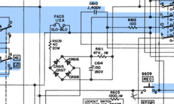
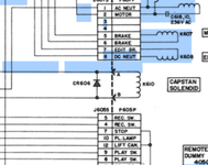
If I trace the capstan solenoid leads, they are connected first to CR606, and eventually the diode bridge by the 1/2 watt fuse.
If I trace the capstan solenoid leads, they are connected first to CR606, and eventually the diode bridge by the 1/2 watt fuse.
Attachments
sweetbeats
Reel deep thoughts...
My mistake.
I’ve never worked on control box issues on an AG-440…I assumed if the lifter solenoid was powered by a 30VDC power rail so would be the capstan solenoid. You’re right. The capstan solenoid is powered by an unregulated rectified line voltage power rail, which makes sense at about +139VDC depending on your local line voltage.
So with the lifter circuit what did you do about relays? Did you replace them? That is the first thing I would do…buy new FFWD and REW relays. And did you check resistance across the EDIT switch terminals? How about verify your remote dummy plug is wired correctly and you have no high resistance contacts in there. You know these old cinch-jones connectors at times need disassembled, de-pinned and then have the contacts treated and deoxidized. You should be inspecting the contacts for bent contacts. I had to replace a couple sockets in one of the connectors on my MM-1000 control box because the sockets were bent. After that, if it still isn’t working I’d suspect a problem with the lifter delay circuit. That’s included in the circuitry connected to terminals E1~E13 on the PCB in the control box. That circuit delays the release of the lifter solenoid when coming to a stop from a fast-wind state to ensure the tape has completely stopped before tape is released to contact the heads. I’d have to read the theory of operation stuff from the main AG-440B manual a little closer while looking at the schematic to understand how it works a little better, but YOU’RE welcome to look at it…pic of page from manual below. It describes in great detail how the entire lifter system works including the release delay circuit. If somebody told me I had to offer some advice before I had time to study the circuit and troubleshoot it myself I’d replace capacitor C621, check all the wiring and solder joints, exercise variable resistor R619, and if none of that helped, I’d shotgun the transistors Q604~Q606, starting the Q606. But mind you that is all after the relays are replaced and the EDIT switch and dummy plug are checked. Those things happen first and I’ve already given that advice, not sure if you’ve done it yet or not, but with this post you have all the help I can offer until you do those things. There is no magic bullet here. You have to tackle the low-hanging fruit of the relays, EDIT switch and dummy plug first before digging into the control box. You have an old machine there with some funky wiring and repairs. So the field of possible causes widens and you have to start at the headwaters.
Speaking of headwaters, can we revisit the +30V power supply? I can’t remember where we left off on that. That is absolutely the first thing you do is verify it is rectified, stable, and can handle a load. Did you load-test it? I can’t remember if you have access to a scope. Did you look at the output of the filter cap C609 with a scope to see if it is clean? Like to determine if the diodes needs replaced? If you don’t have a scope did you at least measure for AC components across C609? One way to load test the supply is to just connect some wires from the + and - side of R602 and connect them to the + and - side of the lifter solenoid directly…bypass the EDIT switch, FFWD and REW relays, lifter release delay circuit, dummy plug, all of that, and just see if the supply itself will make the solenoid actuate. It should jump. To be safe you can connect your wires with the machine powered off and unplugged, then plug it in and switch it on and the solenoid should actuate crisply. If it doesn’t, and if the voltage ramps up all the way at the headwaters, you have an issue with the bridge or possibly the power transformer itself.
Reporting back here.
Some short answers to your questions, and thanks so much for all the tips.
I still haven't bought any new relays. Is studioelectronics the only place to buy them? I swapped the relays one by one with an extra I had laying around. It is out of the back of a parts unit, so it is not known whether it is good or not. But no change in symptoms. (but I can't rule out that I may have replaced a bad relay with a bad relay when I was swapping/testing)
Resistance across the edit switch is 0 ohms. I de-oxed it anyway.
I haven't scoped the 30V supply (admittedly I need to learn more about my scope. Have only been using the X/Y pattern for azimuth alignment)
I haven't tried activating the solenoid by tapping upstream yet.
But I may have found something. I'm getting solid 27VDC (referenced to E2 ground) after rectification all the way to E7, which connects directly to the solenoid. The other side of the solenoid connects to E8, and that's where I'm seeing the ramping up (again referenced to E2 ground). I thought I'd pull diode CR613 and check it because it's inbetween the E7 and E8.
I'm getting 90k ohms in one direction, and infinite resistance in the other. Sounds like at least that one needs replacement. Should be low resistance in one direction right?
sweetbeats
Reel deep thoughts...
I still haven't bought any new relays. Is studioelectronics the only place to buy them?
What? No…they are really common…used in all sorts of machines in industry…bowling machines…you name it. Just get on your favorite web search engine and search for 24V 4PDT or “4 form C” ice cube relays. You’ll get all sorts of hits. You can check eBay too…not hard to find…Mouser…Digikey…Newark…
I swapped the relays one by one with an extra I had laying around. It is out of the back of a parts unit, so it is not known whether it is good or not. But no change in symptoms. (but I can't rule out that I may have replaced a bad relay with a bad relay when I was swapping/testing)
Yeah you already know what I’m going to say…unless you test that spare relay you are really just chasing your tail unless you know you’re not. Since symptoms didn’t change at all it is quite possible all your relays are fine. They are easy to test though…the pinout is usually printed right on the relay itself, and the control box schematic shows you which pins are the common signal pins (9, 10, 11 & 12), and which ones are the outputs…you just set your DMM to resistance, measure between each pole’s common pin and the respective pin to which each connects when the coil is de-energized (pins 1, 2, 3 & 4 for common pins 9, 10, 11 & 12 respectively), then apply 24VDC to the coil pins and do the same test but between each pole’s common pin and the respective pin to which it connects when the coil is energized (pins 5, 6, 7 & 8 for common pins 9, 10, 11 & 12 respectively). Now, this won’t necessarily reveal a dodgy relay, but it *will* reveal a relay with one or more bad contacts or a bad coil.
Resistance across the edit switch is 0 ohms. I de-oxed it anyway.
Okay, fair enough. Good to know and rule out.
I haven't scoped the 30V supply (admittedly I need to learn more about my scope. Have only been using the X/Y pattern for azimuth alignment)
If you know how to use your scope to check azimuth you can scope a power rail. You just use one probe. What kind of scope do you have again? Just set your scope to monitor channel one and put your probe on the ‘+’ side of C609…that’s the 500uF filter cap at the output of the 30VDC supply bridge rectifier CR601~604. You should see a relatively flat line on the scope display. A flat line is DC. You’ll see some waveform there as you zoom the vertical axis (VOLTS/DIV) for channel one. If the waveform is “noisy” you can clip the ground clip of the probe to the control box chassis. Take a pic of the zoomed in display, post it here and tell me if you are using 1X or 10X probes and what the VOLTS/DIV is set to.
I haven't tried activating the solenoid by tapping upstream yet.
Okay. If you do do that, it will rule out if there’s a problem with the solenoid itself, but I’m thinking the issue is on that PCB with the lifter return delay circuit.
But I may have found something. I'm getting solid 27VDC (referenced to E2 ground) after rectification all the way to E7, which connects directly to the solenoid. The other side of the solenoid connects to E8, and that's where I'm seeing the ramping up (again referenced to E2 ground). I thought I'd pull diode CR613 and check it because it's inbetween the E7 and E8.
I'm getting 90k ohms in one direction, and infinite resistance in the other. Sounds like at least that one needs replacement. Should be low resistance in one direction right?
E2 is not the ground reference for the +30V supply. The DC common for the +30V supply comes off the bridge rectifier and goes straight to pin 8 of the remote dummy plug…from there it straps to pins 7 and 12 of the dummy plug. Best place to access it is to clip your meter probe to the ‘-‘ side of that same filter cap C609. You’ll get a more accurate measurement of the +30V supply amplitude if you do that.
You don’t want to measure voltage at E8 by referencing E2…again, that’s the ground for a different circuit. In fact if you look at it, E8 is the ground side for the lifter solenoid. So by measuring between E2 and E8 you’re just measuring the differential between two grounds through the lifter return circuit. E7 is +30V, E8 is the ground reference for the lifter solenoid coil and the lifter delay circuit delays that connection going open to ground under certain conditions. So put the transport in FFWD or REW and measure for DC volts between E7 and E8.
CR613 is not strapped across E7 and E8. It is in series with terminal E8. It prevents current from flowing back through E8. Silicon diodes generally drop the voltage by about 0.7V because there is inherent resistance in the component. Maybe 90R is completely appropriate. I prefer to test a diode using a diode checker. Do you have one? The diode tester applies a small voltage across the diode…in one direction the current should be blocked, in the other current should pass and the tester will tell you if the current flow is restricted (fail) or flows as it should. So it’s an active test rather than passive. You might have a diode test function on your DMM.
I still want to know if you replaced C621 when you recapped the control box? I think that sets the baseline for the time delay. Generally those old metal can axial caps like the Sprague parts stand the test of time really well. I don’t know if that’s the type of part that’s installed at C621, but it wouldn’t hurt to replace it. It’s just that those parts are less prone to early failure. If you ever find those paper can Beaver brand caps those must be replaced asap. Terrible. But those are usually larger value parts like 150uF and up.
A little bit of an update here after having to remove the solenoid to attach a lead again. That wasn't very fun. Anyway, the solenoid definitely strongly activates if I source it's power directly from the headwaters at C609. So it seems good.
Voltage between E7 and E8 at those pins is definitely confirmed to be this ramping up voltage (starts about 11VDC)
I did replace C621, though I see now it's a bi polar elecrolytic I used. But I don't think it should matter?
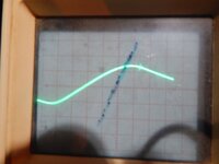
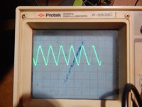
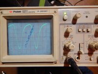
Also, i attached my scope to the (+) and (-) of C609. Also tried to ground the scope to chassis, but the wave form is more rough that way. I don't have a camera with me at the moment, but reading DC, if I zoom in to get the classic sine wave, the top side is definitely clipping. Doesn't seem to matter much the volts/DIV setting (50mV to 5V) , and the Time/DIV setting is 1-2ms to see the DC sine wave. The top side of the wave form is definitely clipped. This is of course a new cap at C609.
Also, i tested the relays to make sure they were close to 0 ohms when not energized. All common to their respective output pins measure close to .5ohm. I didn't measure them energized yet as that's a bit more complicated.
Voltage between E7 and E8 at those pins is definitely confirmed to be this ramping up voltage (starts about 11VDC)
I did replace C621, though I see now it's a bi polar elecrolytic I used. But I don't think it should matter?
Also, i attached my scope to the (+) and (-) of C609. Also tried to ground the scope to chassis, but the wave form is more rough that way. I don't have a camera with me at the moment, but reading DC, if I zoom in to get the classic sine wave, the top side is definitely clipping. Doesn't seem to matter much the volts/DIV setting (50mV to 5V) , and the Time/DIV setting is 1-2ms to see the DC sine wave. The top side of the wave form is definitely clipped. This is of course a new cap at C609.
Also, i tested the relays to make sure they were close to 0 ohms when not energized. All common to their respective output pins measure close to .5ohm. I didn't measure them energized yet as that's a bit more complicated.
sweetbeats
Reel deep thoughts...
Post a pic of the waveform at the output of C609 when you can. It’s probably fine. There is still typically some AC ripple at the output of the primary filter cap that follows a bridge rectifier. And it looks like a truncated sine wave, but it should t be much so it will be important to tell me what your vertical and horizontal settings are.
If Ampex put a polar cap at C621, I would not replace it with a non-polar part. You have a circuit there that is likely not biased for a non-polar part and you could have current flowing the wrong direction. Replace C621 with the proper pert before you do anything else.
If Ampex put a polar cap at C621, I would not replace it with a non-polar part. You have a circuit there that is likely not biased for a non-polar part and you could have current flowing the wrong direction. Replace C621 with the proper pert before you do anything else.
Okay, C621 replaced with proper polarized cap.
Ignore the sharpie somebody put on there. Notice that little feather looking thing after the wave peak. Measuring at .1V gets that more obvious clipping pattern. Leads have no 10X markings so I'm assuming they're 1X. The settings for the three pics are
Volts/Div Time/Div
1V .2mS
.1V 2mS
1V 2mS
Ignore the sharpie somebody put on there. Notice that little feather looking thing after the wave peak. Measuring at .1V gets that more obvious clipping pattern. Leads have no 10X markings so I'm assuming they're 1X. The settings for the three pics are
Volts/Div Time/Div
1V .2mS
.1V 2mS
1V 2mS
Attachments
sweetbeats
Reel deep thoughts...
I’m a bit baffled…when you change the vertical setting from 1V to 0.1V that should increase the waveform by 10x, but it looks like it only increased about 1.6x…
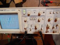
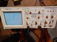
Can you post a pic of the whole face of the scope, maybe from a couple different angles so I can see all of the control settings?
Also, does your scope have an onboard calibrator? It’s usually a square wave generator of some amplitude and frequency so you can probe it and verify what’s on the display matches what the generator is producing.
2V of ripple at the output of a primary filter cap of 30VDC seems like a lot.
Probably the discrepancy is coming from the fine tuning knob on top of the switch, which is more than fine tuning. Similar switch/pot combo like API. See pics. I'll see if I can locate the manual and calibration procedure. Would be nice if I can narrow it down to the delay circuit board or not. I don't mind shotgunning parts on there.
Attachments
sweetbeats
Reel deep thoughts...
The VAR controls should have a defeat lockout position when rotated fully CW. Lock them out.
You can shotgun parts whenever you like but that doesn’t address the fact that, at least with what evidence we have right now, your +30V supply is not right. Maybe it is right, but your scope readings are telling me you’ve got around 2V of ripple.
You have a cal lug on the top right. It says CAL .5V. Look in your manual for what is generated there…DC, square wave, etc. once we know what it is you just clip a probe to that and what’s on the display should match up.
Okay,
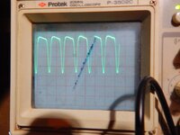
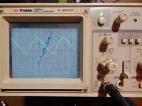
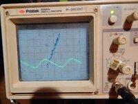
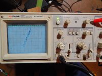
Well, maybe this will make it slightly more clear. Pics didn't upload in the right order, but, you can see the square wave cal reference. This is measured at 5mV with the potentiometer all the way to the right. The other pics are at the cap again. Pic 1 is at 2V, nothing changed except Voltage setting switch. Pic 2 is at .2V, but with the pot rolled back to about 9:00, which is the only way I could get waveform to show up at that setting. Pic three is 5V, again with the pot all the way to the right,
Well, maybe this will make it slightly more clear. Pics didn't upload in the right order, but, you can see the square wave cal reference. This is measured at 5mV with the potentiometer all the way to the right. The other pics are at the cap again. Pic 1 is at 2V, nothing changed except Voltage setting switch. Pic 2 is at .2V, but with the pot rolled back to about 9:00, which is the only way I could get waveform to show up at that setting. Pic three is 5V, again with the pot all the way to the right,
Attachments
sweetbeats
Reel deep thoughts...
So, I didn't really want to get into any oscilloscope operation training, because I'm relatively novice at it myself...I realize you're not necessarily expecting or asking me to do that, but if I were you I know I'd be hoping...been there dozens if not hundreds of times on various issues/projects. I want you to read your scope manual, watch YouTube videos...whatever...to elevate your understanding of how to use and operate your oscilloscope. I'm not meaning to be condescending or anything, I'm just pushing you, because you have it, you're using it, I think you want to understand it better, and I want to help you but I've got limited time and your last post causes me to ask a lot of questions. When you are posting updates *please* be as agonizingly specific as possible, because the details really do matter...making assumtions about what somebody means in this medium and process is just a bad waste of everybody's time.
*What* is 5mV? The channel 1 VOLTS/DIV control? If so, do you understand what that control does and what those settings mean with that control? And by "the potentiometer" are you talking about the channel 1 CAL control? I *think* that's safe to assume, but I've wasted too much time making assumptions when it turns out I wasn't clear or somebody didn't understand but was apprehensive to just say so, and/or they thought I meant something else and I think they mean the same thing I think they do...ugh.
If my assumptions above are correct and additionally you don't really know what those settings mean or what to do with them on the TIME/DIV controls for channels 1 & 2, they control how far zoomed in or out you are in the vertical or 'Y' axis of the scope display for the respective channel. Oscilloscopes do many things for us. Two of the main ones are they 1. allow us to SEE electricity...visualize the electrical waveform, and 2. to MEASURE the overall waveform...the amplitude and frequency. Again, an oscilloscope can do many, many more things, but for guys like you and me its often about amplitude and frequency, sometimes visualizing distortion, and also setting azimuth in X-Y mode. Okay...back on track.
Notice the scope display has a grid...so when you have the vertical axis set at 5mV, that means each mark or "division" (i.e. DIV) of the grid represents 5mV...volts per division (VOLTS/DIV)...if your waveform measures 7 divisions from peak-to-peak (in other wirds from the lowest point in the wave to the highest point), the voltage of the source is 7 x 5mV = 35mV. The ability to do the math of taking your vertical axis control setting and comparing the waveform to the divisions on the scope display only holds true if the channel is in the CAL position (CAL control usually rotated fully clockwise and usally there is a click or detent when the control is set to CAL). If the waveform is too big to see on the display, you're zoomed in too far...DON'T DICKER WITH THE CAL CONTROL TO REMEDY THIS. Just...zoom out a click on the VOLTS/DIV control..or two clicks...or whatever you need to do to see the whole waveform...and the opposite is true...if you can just barely see anything more than a flat line of a source signal you know is AC, zoom in. But do it with the VOLTS/DIV control and not the CAL control, because that way you can alway do the math and measure...or the guy on the forum can do the math...because we are trying to determine if your +30V supply has a problem...we are trying to verify whether or not AC ripple at the output of DC power supply's primary filter cap is in an order of magnitude of volts...which is bad, because it should be millivolts...if you get a waveform triggered on your display and were trying to quanitfy the amplitude, but you pull the channel out of the CAL setting, now its impossible to quantify the voltage of the waveform because we can no longer do the math.
And ahead of that the other thing we're trying to do first is to determine if your scope is displaying correctly. A known square wave signal is present at the calibration lug, okay? You probe that and your scope should display a square wave. So what? We don't stop there...we need to set our vertical axis and horizontal axis in a way that we can see the entire waveform, look at the vertical and horizontal control settings, do the math, and compare to the specifications of the calinration signal. We already know the voltage right? I stated it in a previous post because its printed right on the face of your scope...0.5V right? Now I want you to look in your manual...in the section where all the controls are numbered and then there is a list describing each control or facet...the frequency is noted there...find that and post it here. Once you have that information, probe the calibration lug again, set your vertical VOLTS/DIV control so you can see the whole waveform from top to bottom, and zoom in so the waveform takes up most of the vertical axis...maximizing the resolution gives a more accurate count of the divisions...then look at where the VOLTS/DIV control is set, and do the math after you count the divisions spanned by the waveform. And then adjust your TIME/DIV control, which is the horizontal axis, zoom that in so you see just one complete wave on the display...look at the TIME/DIV control at what the time per division is, and do the math after you count the divisions for the complete waveform (and for a square wave that's from the beginning of the top to the end of the bottom), which will give how many milli or micro seconds the wave is, and you can convert to Hz or kHz...if you don't know how to do that just say so and I'll help. Once we have all that math done we can compare what we measure on the display and compare to what its supposed to be coming off the calibration lug. With that we know if your scope is measuring and displaying accurately. THEN we can start looking at your power supply output.
"The cap..." The primary filter cap C609?
What is at 2V? The vertical axis VOLTS/DIV control on the scope? And I have no idea what voltage setting switch you are talking about.
Again, what is 0.2V? The VOLTS/DIV control? And "the pot..." are you talking about the CAL control?
Same questions as above.
Question for you:
The horizontal bank of switches on your scope at the top of and in betweem the channel 1 and channel 2 vertical axis controls...those mode switches labeled CH1, ADD and CH2...in the pics you posted which switch or switches are latched?
...you can see the square wave cal reference. This is measured at 5mV with the potentiometer all the way to the right.
*What* is 5mV? The channel 1 VOLTS/DIV control? If so, do you understand what that control does and what those settings mean with that control? And by "the potentiometer" are you talking about the channel 1 CAL control? I *think* that's safe to assume, but I've wasted too much time making assumptions when it turns out I wasn't clear or somebody didn't understand but was apprehensive to just say so, and/or they thought I meant something else and I think they mean the same thing I think they do...ugh.
If my assumptions above are correct and additionally you don't really know what those settings mean or what to do with them on the TIME/DIV controls for channels 1 & 2, they control how far zoomed in or out you are in the vertical or 'Y' axis of the scope display for the respective channel. Oscilloscopes do many things for us. Two of the main ones are they 1. allow us to SEE electricity...visualize the electrical waveform, and 2. to MEASURE the overall waveform...the amplitude and frequency. Again, an oscilloscope can do many, many more things, but for guys like you and me its often about amplitude and frequency, sometimes visualizing distortion, and also setting azimuth in X-Y mode. Okay...back on track.
Notice the scope display has a grid...so when you have the vertical axis set at 5mV, that means each mark or "division" (i.e. DIV) of the grid represents 5mV...volts per division (VOLTS/DIV)...if your waveform measures 7 divisions from peak-to-peak (in other wirds from the lowest point in the wave to the highest point), the voltage of the source is 7 x 5mV = 35mV. The ability to do the math of taking your vertical axis control setting and comparing the waveform to the divisions on the scope display only holds true if the channel is in the CAL position (CAL control usually rotated fully clockwise and usally there is a click or detent when the control is set to CAL). If the waveform is too big to see on the display, you're zoomed in too far...DON'T DICKER WITH THE CAL CONTROL TO REMEDY THIS. Just...zoom out a click on the VOLTS/DIV control..or two clicks...or whatever you need to do to see the whole waveform...and the opposite is true...if you can just barely see anything more than a flat line of a source signal you know is AC, zoom in. But do it with the VOLTS/DIV control and not the CAL control, because that way you can alway do the math and measure...or the guy on the forum can do the math...because we are trying to determine if your +30V supply has a problem...we are trying to verify whether or not AC ripple at the output of DC power supply's primary filter cap is in an order of magnitude of volts...which is bad, because it should be millivolts...if you get a waveform triggered on your display and were trying to quanitfy the amplitude, but you pull the channel out of the CAL setting, now its impossible to quantify the voltage of the waveform because we can no longer do the math.
And ahead of that the other thing we're trying to do first is to determine if your scope is displaying correctly. A known square wave signal is present at the calibration lug, okay? You probe that and your scope should display a square wave. So what? We don't stop there...we need to set our vertical axis and horizontal axis in a way that we can see the entire waveform, look at the vertical and horizontal control settings, do the math, and compare to the specifications of the calinration signal. We already know the voltage right? I stated it in a previous post because its printed right on the face of your scope...0.5V right? Now I want you to look in your manual...in the section where all the controls are numbered and then there is a list describing each control or facet...the frequency is noted there...find that and post it here. Once you have that information, probe the calibration lug again, set your vertical VOLTS/DIV control so you can see the whole waveform from top to bottom, and zoom in so the waveform takes up most of the vertical axis...maximizing the resolution gives a more accurate count of the divisions...then look at where the VOLTS/DIV control is set, and do the math after you count the divisions spanned by the waveform. And then adjust your TIME/DIV control, which is the horizontal axis, zoom that in so you see just one complete wave on the display...look at the TIME/DIV control at what the time per division is, and do the math after you count the divisions for the complete waveform (and for a square wave that's from the beginning of the top to the end of the bottom), which will give how many milli or micro seconds the wave is, and you can convert to Hz or kHz...if you don't know how to do that just say so and I'll help. Once we have all that math done we can compare what we measure on the display and compare to what its supposed to be coming off the calibration lug. With that we know if your scope is measuring and displaying accurately. THEN we can start looking at your power supply output.
The other pics are at the cap again...
"The cap..." The primary filter cap C609?
Pic 1 is at 2V, nothing changed except Voltage setting switch.
What is at 2V? The vertical axis VOLTS/DIV control on the scope? And I have no idea what voltage setting switch you are talking about.
Pic 2 is at .2V, but with the pot rolled back to about 9:00, which is the only way I could get waveform to show up at that setting.
Again, what is 0.2V? The VOLTS/DIV control? And "the pot..." are you talking about the CAL control?
Pic three is 5V, again with the pot all the way to the right,
Same questions as above.
Question for you:
The horizontal bank of switches on your scope at the top of and in betweem the channel 1 and channel 2 vertical axis controls...those mode switches labeled CH1, ADD and CH2...in the pics you posted which switch or switches are latched?