aardvark q10 users - Volume knob repair?

jrich

New member
For anyone using an aardvark q10, or knowing anything about its electronic components, I wonder if anyone knows how to help me.

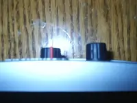
I recently purchased a second unit off of ebay and it functions properly, EXCEPT that both the monitor and headphone volume knobs are busted. It appears as though they were forced into the box, and when I opened it they were busted inside. I believe this happened during shipping, but fedex's claim process is like pulling teeth and I'd rather just try to fix it.

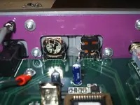
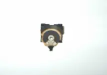
Does anyone know what type of knobs are used for the volume controls?? I don't really know anything about electronics, but it appears that they just have two connections soldered to the board with the knob in between the signal. I would assume these are just potentiometers, but I don't really know. I took it to an electronics repair store in town and he just plain said he couldn't fix it, didn't even have a suggestion as to what kind of part it could be.

any help would be awesome!
josh
 
*bump*

Thought I'd give it one more shot. Nobody with electrical experience out there using a q10?
 
Hello, fellow Q10 user. lol. I have never opened my Q10 up and looked inside, but unless the controls are just stepping controls for a potentiometer IC, then they should be standard 500k OHM audio taper pots. You can get them from Radio Shack for about a buck a piece. Do you have some pictures of the controls so we could see the damage? I can give you a better idea of where to go from there if I could see the unit.
 
Here's some pics.

Thanks for taking a look prodecer kid. Here are some pics. The first is an overhead of the knobs to show what happened. They got pushed in. The second shows how the backs got busted out. The one on the left is the headphone knob. The one on the right is monitor volume with the plastic still there. The third pic is what was broken off of the headphone volume that is still on the monitor volume part. Sorry about the blurry pics, it was the best I could get with my camera.

josh
 

Attachments

  • overhead knobs.jpg
    overhead knobs.jpg
    35 KB · Views: 12
  • inside busted controls.jpg
    inside busted controls.jpg
    50.6 KB · Views: 12
  • broken piece.jpg
    broken piece.jpg
    9.7 KB · Views: 11
these appear to be standard audio taper potentiometers most likely 500k ohm. they can be replaced with some light soldering work. if you cannot find anyone in the area to do the repair for you, i am not quite sure what to tell you. an easy fix for the monitor control would be to pull te control out of the box and short pins 2 and three together, bypassing the control and use the volume controls on your speakers or power amp to control the volume. for headphones, get an inexpensive headphone amp to control the headphone volume coming from the headphone jack, and perform the same fix to the headphone volume pot. short pins 2 and 3 to bypass the control. if this sounds like something you might not be able to do yourself, i could try and help you if you like. if you pay for the cost of shipping the unit to and from me, and for the cost of the replacement controls (no more than $10 for both) i can repair it for you if you like.....thats about the only thing i can offer.

of course if you want to sell it and the card, ill be happy to take it off your hands :D :p
 
Thanks for the tips.

I am somewhat comfortable doing light soldering work as I've done it before. I figured they were just potentiometers, which is why I was surprised the only electronics repair place in town said they couldn't fix it. I think I could just put new pots in because I have powered monitors so no volume control, and it'd be cheaper for the headphones than buying an amp (though I'll need one eventually anyway)

A couple more questions. You mention pins 2 and 3. I only see two connections. Is pin 1 not connected? I remember reading somwhere about not connecting the ground for volume control. I think the only thing that might confuse me is which two pins to connect when I do buy a new pot..am I correct in assuming that all or most will have 3 pins?

Thanks producer for all your help!
josh
 
The two connections that you are seeing are the casing (ground) nips to the board. the actual pot connections are going to be three smaller legs in between the big metal ones. follow the traces on the board to the pot and see where they lead. the pot may be installed to where the legs wrap under the board and are surface soldered. im not sure which. you will most likely have to pull the board out to accomplish the job.
 
Back
Top