3M M64 Halftrack

I totally figured out how to disassemble the capstan. A whole new level of mass and precision is this capstan assembly. I literally uttered "Oh wow".
 
I am really enjoying sprucing this thing up. I'm getting pretty close to having all the visible cosmetic stuff cleaned up, but there is very little to do. I took a paintbrush and vacuum to the chassis and with very little effort (I'm not kidding) this thing looks like a new machine. I've never experienced a machine that cleaned up this nice and easy...no kidding...and this is probably the oldest machine with which I've ever worked.

I need to polish a couple more parts and clean up the capstan assembly from my parts machine, but I'm just about ready to reinstall the capstan and 15/30ips capstan motor from the parts machine and put all the cosmetics back on and then it will be ready to rack up.

BTW, the belt is the same type as in my Ampex MM-1000: mylar.

Here is a great example of how nice this machine is cleaning up...the transport buttons...look at them. Usually this is an area that experiences high wear but these look like they could pass for new. And I only spent about 5 minutes cleaning up what little needed cleaning:

IMG_3394_1_1.JPG


IMG_3395_2_1.JPG


IMG_3396_3_1.JPG
 
Revisiting post #61 here...I pulled both capstan assemblies in hopes that there would be a good set of bearings between the two assemblies. Bingo.

And that's good.

These bearings are about $100 a pop and there are 3 of them: 2 at the top and 1 at the bottom.

This assembly is a precision piece of work and it's hefty.

This is the shaft housing in my hand...obviously this does not include the flywheel or the actual capstan drum which attaches to the nose of the shaft:

IMG_3402_2_1.JPG


Here are all the parts of the entire capstan assembly:

IMG_3399_1_1.JPG
 
Yeah, those keycaps look good. Mostly found with engraving worn off, or engraving worn off AND the paint that surrounds the button, now thats some milage!
 
Getting it put back together.

Here is the underbelly of the transport at the moment:

IMG_3443_2_1.JPG


That's the 15/30ips capstan motor peeking out below the flywheel.

I AM having some trouble with the flywheel not spinning true though...there is visible axial wobble. I put a dial indicator on the shaft itself to measure the runout and there is about 0.0005" of runout which could translate to thousandths of an inch at the edge of the flywheel. I thought "ahhhh I'll just swap in the other capstan shaft" which I did annnnnd...same thing. I thought "maybe the flywheel is goofy..." Swapped out the flywheel, same thing. Then I tried the combination of the original capstan shaft and the parts flywheel....saaaaaaaaame thing. I'm wondering if, for some whacky reason it was made that way. I can't really think of a good reason why, and, granted, if there ARE any artifacts generated by the abnormality I'd expect them to be so far below the LF knee point, but still...I'd think the capstan shaft would be one place you DEFINITELY wouldn't want goofiness. I'm going to cast the question out to a couple people to see if I need to mess with this or not.

Cleaned up partially reassembled top-side:

IMG_3444_3_1.JPG


And a zoom in on those transport buttons:

IMG_3445_4_1.JPG


I got a box of new lamps for the controls.

I also got a new lamp for the optical sensor assembly.

Here is another random shot...I just like all the round things...

IMG_3446_5_1.JPG


Anyway, coming along...and I did power it up to test and make sure my capstan swap worked and it did.

Still can't get over how clean this thing is.

Oh, and my friend from whom I got this thing accidentally forgot to include the harnessing that interfaces the transport and the electronics, so that's on the way along with an OEM power cord. Cool.
 
Last edited:
Perhaps the .00005 wobble is a product of the transport being in the vertical position when measured, as apposed to being in its normal horizontal orientation?

Oh, and the clean up, of what little was needed, looks real nice! :)

Cheers! :)
 
You couldn't get 0.0005" of play on that thing if you tried. The upper bearings are angular thrust bearing in opposing orientation...it is VERY smooth and tight...naw...something isn't right. At the flywheel edge there is 0.012" of vertical runout and 0.0025" of radial runout. I'm dialoging with Dale Manquen about it. It isn't supposed to be that way so I'm going to have to figure it out.
 
I ended up trying different combinations of the two capstan shaft assemblies and the two flywheels to see if I had some damaged parts or if it was "normal" for there to be vertical and radial runout on the capstan flywheel. No matter what combination I tried there was still both vertical and radial runout.

Bummer.

I got in touch with Dale Manquen and he kindly offered to go check an M-56 transport to see if there were similar issues. There were. Upon closer inspection the vertical runout was not translated to the crown along the outer edge upon which the capstan belt rides, and vertical runout, even if present in the belt's driving surface, shouldn't have significant impact in the flutter. The radial runout would contribute to flutter. Dale walked me through some calculations and basically what it comes down to is that anything under approximately 0.0025" of radial runout on the flywheel shouldn't cause the overall flutter performance to exceed the factory spec of 0.04%. I'm sitting at about 0.0015" radial runout so it should be fine.

So the capstan assembly is back in with belt installed and tensioned and covers on.

Right now I'm working on adapting my Ampex instrumentation reel adapters from a 440-8 I used to have to the reel tables of the M-64. Why? I love these reel adapters because they self-center the reel on the table while clamping. I hesitated to even go this road because I didn't know if the appearance of the Ampex adapters would be odd looking, and I also wasn't too interested in drilling holes in the 3M reel tables...just didn't want to risk messing them up. What I hadn't really paid attention to before is that there are a bunch of extra holes in the reel tables...see?

IMG_3490_1_1.JPG


The three center holes are the mounting holes that fix the table to the motor hub, but the two other sets of three holes? Who knows, but I thought "wouldn't that be freaky if those holes matched up with the Ampex reel adapter?"

So I pulled the trident post off the reel table...

IMG_3493_3_1.JPG


And took the Ampex reel adapter which looks like this:

IMG_3492_2_1.JPG


Stripped it down to the base and held it up to the 3M reel table and wouldn't you know it? Perfect match:

IMG_3496_4_1.JPG


So I'm going for it. One of the adapters is already refurbished, and obviously the one pictured above is awaiting that same treatment, but I took the clean one and put it up to the transport and the finish on the adapter parts is identical to the finish on all the cast aluminum parts on the M-64. I think it'll look nice.
 
Last edited:
Cory,

Glad to read the radial run out is within spec. I suspected that it probably was, but didn't have the technical numbers to back up that feeling. Also cool to see the Ampex/3M reel clamper/reel table marriage. I'm sure they'll enjoy wedded bliss! :D

Cheers! :)
 
I don't think flywheels ever spin perfectly true. According to DaveD, that's why they drill out the balance holes on the 440's. I don't know about this one. But I guess it depends how severe it is.
 
Got some of the trim metal installed as well as one of the Ampex instrumentation reel adapters. I came up with a way to get the adapter concentric within 0.002" relative to the hub. I powered up the transport with a reel clamped on and put it in fast-wind to see how bad any vibration was. I'm pleased with the results. These instrumentation adapters offer a positive clamping hold on the reel and center the reel on the table.

I slipped the main dress panel in for a couple of the shots. Its a handsome machine. And oh my GOODNESS does the motor get hummin'...I need to shoot some video. Its impressive.

WP_000453_1_1.jpg


WP_000456_2_1.jpg


WP_000457_3_1.jpg


WP_000458_4_1.jpg


My apologies for the lame picture quality...mobile device...not bad all things considered, but still not too hot.
 
Last edited:
Those Ampex NAB hub adapters look very much at home on the 3M!

Question;

Can they be easily removed if you needed to play a smaller 7" reel on the machine?

Cheers! :)
 
They can be removed without disassembling the adapter, but then disassembly is required to get the adapter centered when reinstalling. Yes I thought about this in advance. All my tape is on 10.5" reels except for the cal tape but I'm going to transfer that to a 10.5" reel.
 
This forum needs a Facebook-style "like" button. I like this! ;)


Funny about the little details, like I couldn't help thinking that the side-facing heads must be somewhat more awkward to clean and de-mag compared to traditional front-facing stacks.
 
This forum needs a Facebook-style "like" button. I like this! ;)


Funny about the little details, like I couldn't help thinking that the side-facing heads must be somewhat more awkward to clean and de-mag compared to traditional front-facing stacks.

Actually, heads seem easier, if anything. Capstan is a bit trickier to reach. Not a big deal either way.

Cheers,

Otto
 
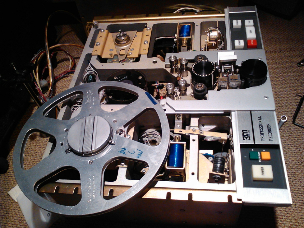
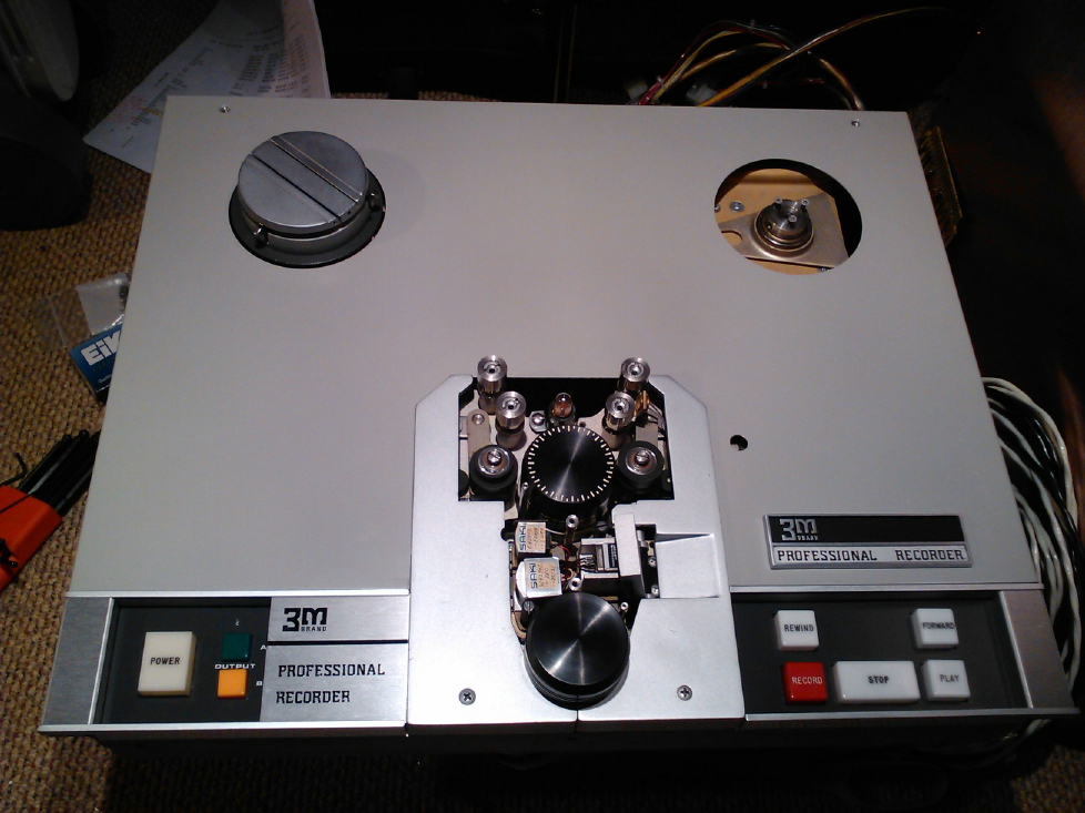
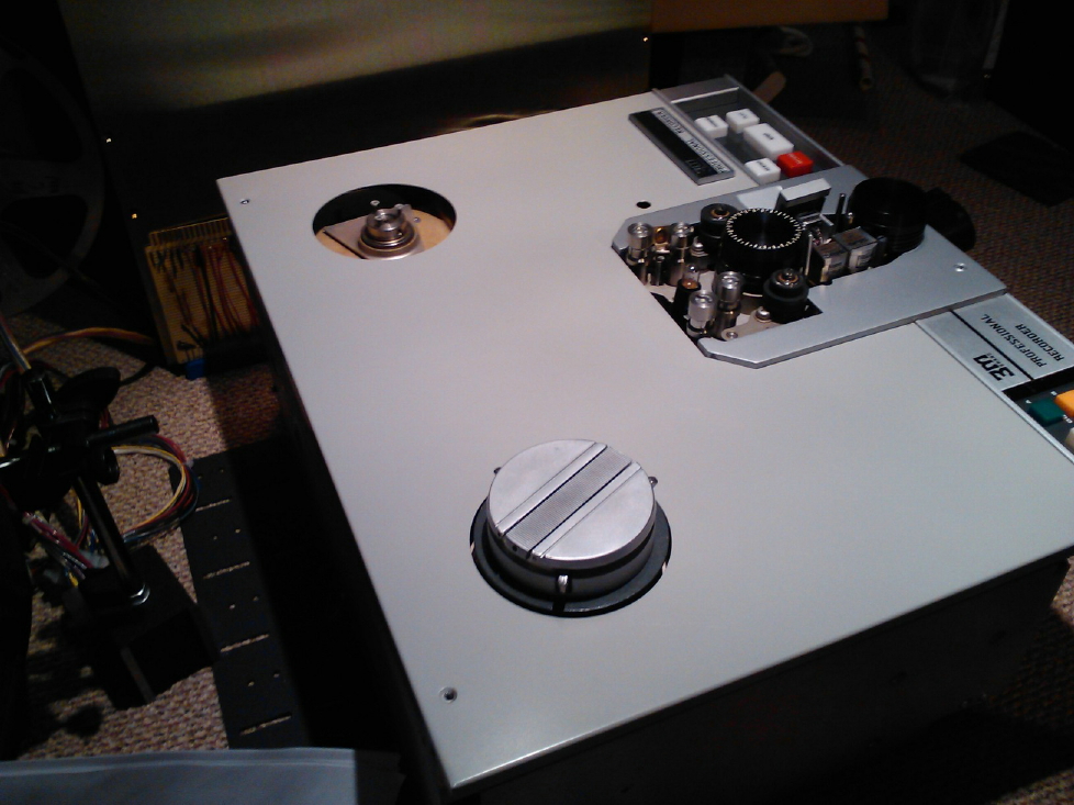
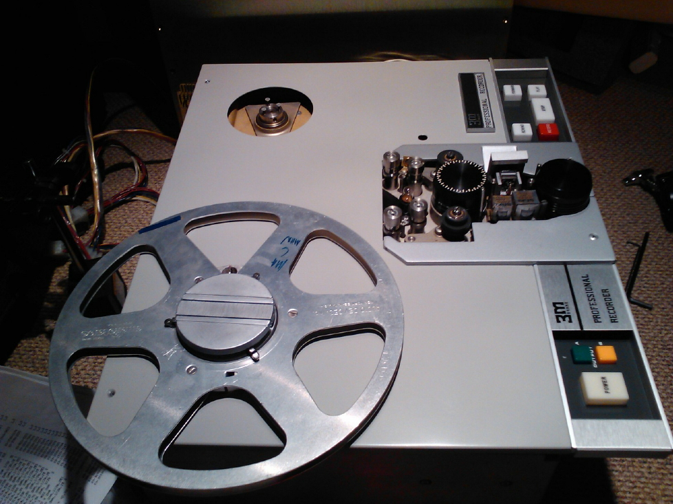
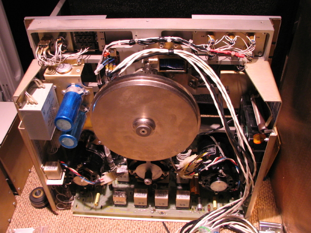
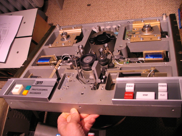
Been awhile, but the M64 is in the studio. The transport is juuuuust about ready to try with "shop" tape...just need to mount a couple small covers on the headblock and reinstall the tape sensor.

The other thing I'm in the midst of is cleaning up and inspecting a couple electronics modules. I have five modules total: the two M64 modules that came with the original machine (which is now my parts machine), and three modules that came with the second transport. Two of those three modules are actually from a 4-track M23 machine, and one of them is an M64 module original to the second transport. No idea where the second original module is. The two M64 modules that came with the original machine are *filthy* and configured for console-mounting which means they do not have VU meters on them. On the console-mounted machines the meters fly above the transport, and the place where the meter is normally mounted on the front of the electronics module (which, coincidentally, is the front of the pull-out power supply module for the electronics module) is replaced by a steel plate with a little drawer pull on it (making it easy to pull the power supply out if needed). Ultimately I'd like to have a custom 3U panel made up by Front Panel Express to rack-mount a pair of meters up by the transport. They did an awesome job making some custom panels for the patchfield modules on my MCI JH-416A desk, so I'll be a return customer for them. ;)

ANYway, my point here is that the two module that came with the original transport are filthy and without meters, and the only other pair of modules I have are the set from the M23 and fortunately they have meters. The differences between the M23, M56 (1" 8-track) and M64 modules are very minor...I think just some minor component differences on some of the amp cards, but the cards are all interchangeable, so away I go to mating up the M23 modules with my M64 transport. Oddly enough the M56 and M64 modules are finished in a dark grey, while the M23 modules are finished in a putty color that actually matches the dress panel on the M23, M56 and M64 transports. Go figure.

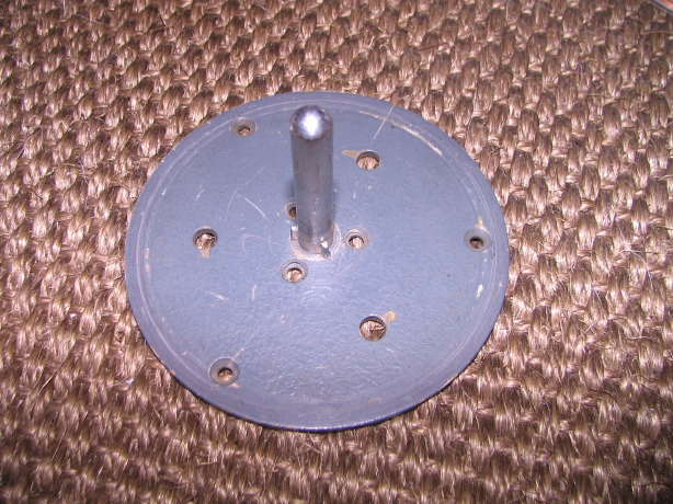
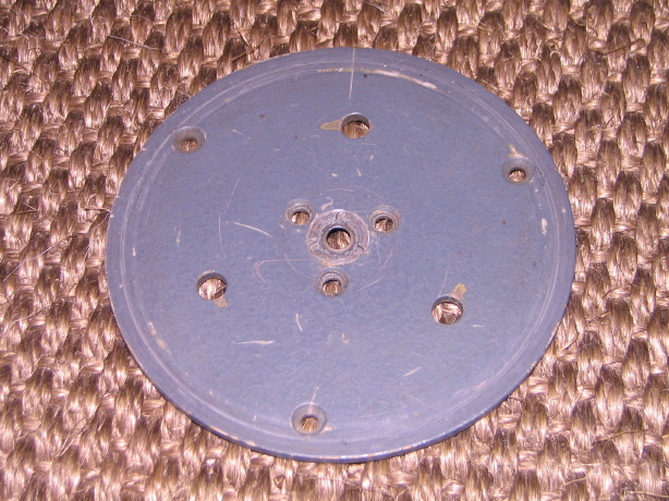
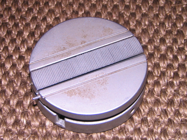
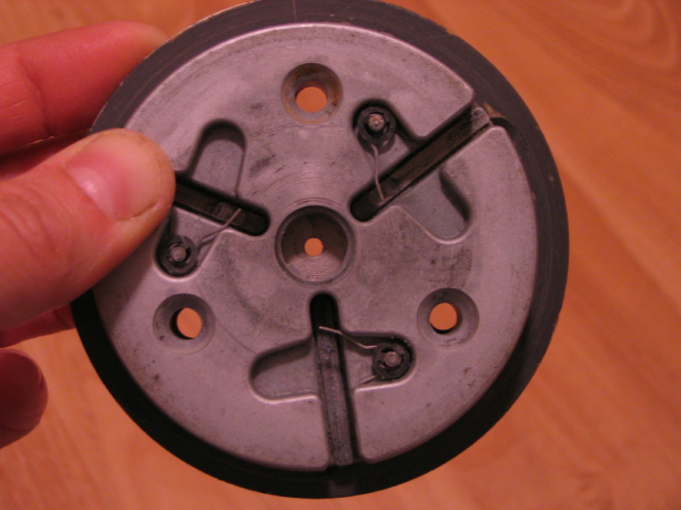
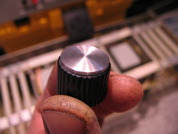
So I've been busy cleaning up and inspecting these two M23 modules. They needed very little. I did some disassembly, got out the window cleaner, iso alcohol, shop vac, toothbrush and various rags and my TR3 polish...the usual regimen. I replaced the screws that mount the control panel to the module frame with stainless screws and washers and found a way to chuck the knobs onto my drill motor so I could polish up the aluminum knob caps. Now mind you these aren't aluminum lookin' stickers...or even little circles stamped out of 16ga aluminum sheet. These are honest-to-goodness aluminum discs actually turned out of aluminum rod...I can see that these were actually machined...its awesome:

IMG_4005_12_1.JPG


So I got all that stuff cleaned up and in the process was just re-impressed with how 3M designed and put this stuff together. Same thing with the transport...the degree of over-engineering is akin to my Ampex stuff, but the engineering of the layout and assembly of components is, IMO, a cut above.

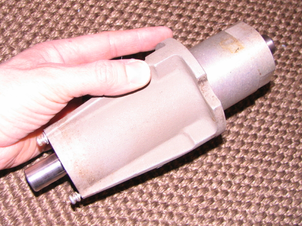
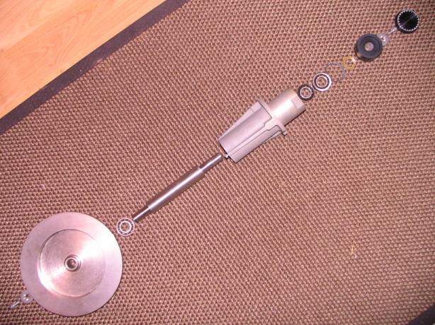
Here is that power supply for the module...this power supply provides filtration and regulation for one channel of electronics, is all discrete and is of plug-in design via a card-edge connector. Its assembled using good ol' threaded fasteners...no spot welds or rivets. Need to take it apart completely? Get out a simple #2 phillips screwdriver.

IMG_3994_4_1.JPG


IMG_3996_5_1.JPG


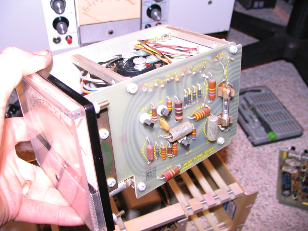
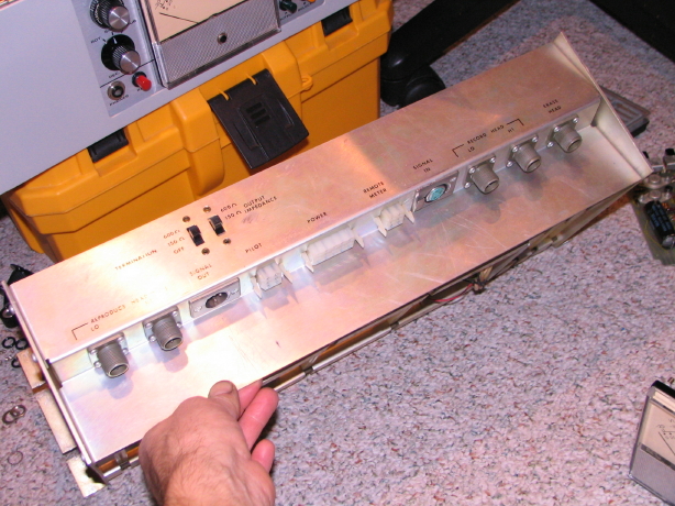
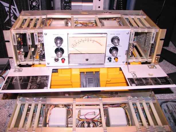
Here is the naked electronics module chassis with the cards, power supply and control panel removed. Notice that the sides are connected together via steel rods with extruded aluminum spacers in between each set of card slots...totally modular. If this chassis needed to be reconfigured for a different number of slots, you remove on end panel and slide the parts off like a shishkabob and slide the new stuff on. As it stands the module has 8 cards slots. Not all are used. Some are empty slots and then there are some slots for the 3M Dynatrack system. I won't go into detail, but if you aren't awware of what the Dynatrack system is it was/is a unique approach to noise reduction and dynamics processing using multiple tracks (i.e. a 2-track machine would use 4-track heads and 4 electronics modules) with differing operating levels and discrete auto-fading between the tracks. Anyway, here is the chassis:

IMG_3998_7_1.JPG


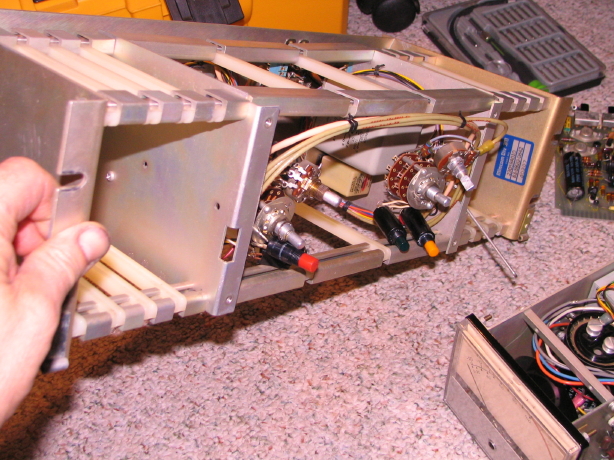
And I love what they did as far as mounting the connections on the back...they are angled facing down to avoid dust and dirt getting into the connections and this also avoids potential damage from connectors protruding out the back of the module:

IMG_3999_8_1.JPG


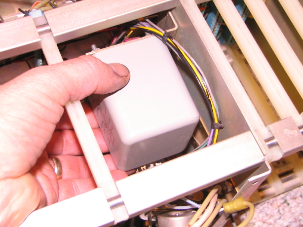
And I still can't get over the size of the input and output transformers. Now let's please keep in mind that transformer coupling doesn't make the sound "better"...it alllllll depends on what is "better" to you. If you're Jim Williams, then "better" is total neutrality...input=output. Others like the distortion and non-linearites that transformer-coupling can add...the color. These transformers have a lot of metal in them. Juuuuust lookit...they're hyooge:

IMG_3997_6_1.JPG


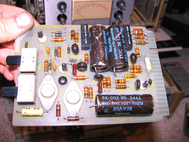
And this is a fun tidbit...I've been having some dialog with a couple folks regarding recapping of the amp cards. One of those folks is Dale Manquen which is awesome because he designed this stuff. Anyway, most of the dialog has been over the output amplifier card. Dale said the circuit was borrowed from a "Fairchild application note on designing a quasi-complementary power amp". Dale said that, back in the mid 60's, he drove his 16 ohm 15" JBL's directly off the card. Crazy. Anyway, this is the card I'm talking about, and yes the old "Beaver" branded caps have got to go!

IMG_4001_10_1.JPG


IMG_4003_11_1.JPG


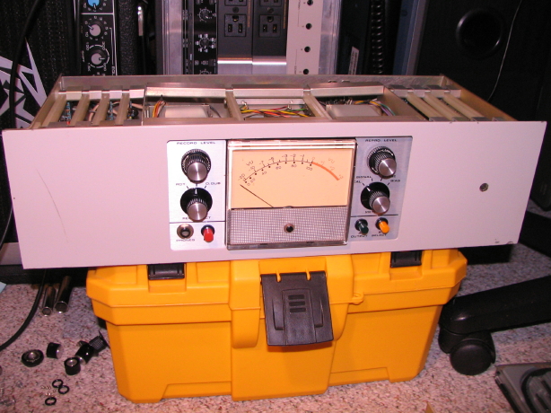
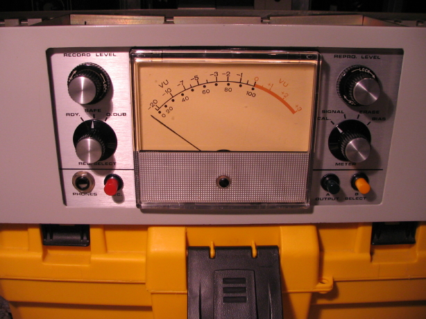
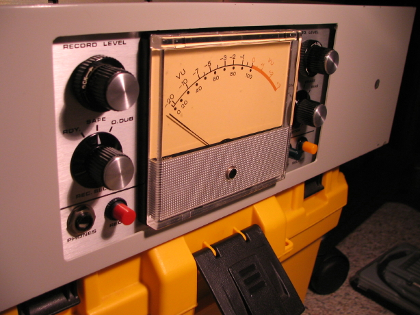
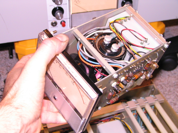
Here is one of the modules cleaned up. Wish I was adept at repainting stuff as the scratches in the front panel really detract from the overall condition, and unfortunately the replacement image sensor on the point-and-shoot camera I was using coupled with the built-in flash makes for terrible pics, but they're better than nothing:

IMG_3990_1_1.JPG


IMG_3992_2_1.JPG


IMG_3993_3_1.JPG


IMG_4000_9_1.JPG


Here is a short youtube video I shot going over a lot of the same stuff I just covered above as far as the construction of the modules:

YouTube


So pretty quick here I'll actually get the modules racked up, cross-connect them with the transport and try powering everything up (after I build a simple manual soft-start circuit...not taking any chances with this first power up...dunno how long its been since these modules have seen power). Then there's a couple things to check on the transport but after that I'll try threading up some "shop" tape and take it for a spin!
 
Last edited:
Awesome progress there, Cory! :)

The construction quality on those units is definitely in a class all its own! Sort of reminds me of the type of engineering level that might have gone into NASA Apollo series space craft with everything over built with the finest materials money could buy!

Your clean up job definitely is making improvements to the look of the units and noticed you even cleaned the inside of the VU meters, which look essentially brand new now!

I hope the power up goes smoothly and that nothing misbehaves on you!

Looking forward to seeing some D-SLR shots of that and getting some nice shots without the flash burn and other "snap shot" artifacts. ;)

Cheers! :)
 
Back
Top