Tascam M520 Story...

I'm up for the challenge, who knows I might even learn what to make of all those numbers and figures ha. I really appreciate the help.
 
So just to be clear, you understand I'm not lifting a finger until you put up a list of caps for me to check right? Unless you can't even get there and have questions...I'll help you get there but you're not gonna get rid of the training wheels unless I let go of the seat.
 
Shouldn't take you all night... :eek:

Just find those caps listed as "Elec."

And there are always two numbers associated with a capacitor: its capacitance (the amount of charge it can store, measured in micro farads or "uF" for the electrolytic caps in the M-500 boards), and the voltage rating...how much power the cap can handle.

Make sure both of these numbers are in your list.

If you're looking at page 141 in the manual you're on the right track...hint-hint...
 
When a 6 hour session turns into a 12 hour session, I call that an all nighter. Well got the binder in hand, thanks for the hint.

Input AMPL. PCB Pg 142
C1, C2 - 22uf - 50v
C7 (bp) - 470uf - 16v
C10, C11 - 47uf - 25v
C12, C13 - 22uf - 25v
C14 - 10uf - 16v
C15 - 47uf 25v
C16 - 100uf - 10v (b,c)
C19 - 22uf - 25v (b,c)
C20 - 10uf - 16v
C21 - 22uf - 25v
C22 - 22uf - 25v
C23 - 22uf - 25v
C24 - 1uf - 50v
C25 - 10uf - 16v
C33, C34 - 10uf - 16v
C35 - 22uf - 25v
C36 - 10uf - 16v (b,c)
C46, C47 - 100uf - 16v
C48 - 10uf 16v
C59, C60 - 47uf - 25v

Is this right? In your opinion what else might I replace while I'm in there? I want to replace one thing at a time, so maybe that question is better saved for later...first caps.
WOW ok so "C" stands for "capacitor". I'm trying to locate the diagram where I can try and make some sense of all this. The manual is crazy, can't seem to locate the channel strip diagram.
 
Question:

Which 4-channel module are you starting with again? 1~4, 5~8 or 9~12? It matters because channels 3 & 4 have some additional caps (noted with the "b,c" suffix).

Information:

  • The "bp" associated with C7 means "bi-polar" or non-polar. The rest of the electrolytic caps on the board are polar (have a + and - orientation and should only be installed with the proper orientation or they explode...not a big deal with little caps...can be dangerous with big caps...)
  • General rule of thumb in my book is to recap the power supply first. Something to think about.


Answers:

  • I can't think of anything else you would need to/want to replace, and your notion of "one thing at a time" is wise.
  • By "channel strip diagram" are you talking about the schematic? See pages 197, 198, and 199.


Assignment:

Take your list you made and group the same caps together so you have a list with total quantities of each type. For instance C14, 20, 25, 33, 34, 36 and 48 are all the same part. So for channels 3 or 4 you need 7 of that one type of cap. Make sense? You make the aggregate list and then you get links to the parts at Mouser.

Questions?
 
So my plan is to start dissembling a parts module I have before moving to the 512. I want to practice my sucking/soldering skills before moving to the real thing. The 512 has an internal power supply, that's why I'm going to start with module 1~4. I will also deoxit the pots and lube the faders. My real goal is to get my 520 up to snuff after the 512 is alive and kicking.

Will it be obvious how the polar caps are orientated? Will the old caps have a + and - sign on them?
I was thinking about replacing the op amps. If I remember right, you said somewhere that you would just leave them be?
If recapping goes well, I wouldn't mind trying an op amp upgrade on one module.

Assignment
A little confused...
C14, C20, C25, C33, C34, C36, C48. If these are all the same, why didn't Tascam just use one type of cap...why label them different numbers? How did you know I need 7 of those caps for channels 3 & 4? Obviously all those add up to 7. I'm looking at pg 197-199. Can't seem to make sense of what I'm looking at. I now understand what the "C" and "R" stands for, but when I look at the schematic and then look at the circuit board, it doesn't look the same to me. It's like that scene in the Matrix where he is looking at the Matrix through the computer screen for the first time. I haven't located the women in the red dress yes:-/ Maybe I'll keep staring....
LIST
10uf - 16v (C14, C20, C25, C33, C34, C36, C48)
22uf - 25v (C12, C19, C21, C22, C23, C35)
47uf - 25v (C10, C11, C15, C59, C60)

Am I close?
 
The Cs and the Rs etc are called reference designators. You see them on the schematic and you will find them marked that way on the circuit boards. This is so when you are troubleshooting looking at the schematics and you want to probe around a certain cap you look on the schematic for its reference designator (say C37), then you find the same reference designator (C37) on the circuit board and go about your business. Even if all the caps on a circuit board were the same value, this is how you link where you are on the schematic with where they are on the board.

The polarized caps (electrolytics) will have markings. Most likely a black band on one side with "-" signs printed on the band. The circuit board will be marked with either a plus or a minus. Line up accordingly.

Yup.

"R" is a resistor. "VR" is a variable resistor (a rotary potentiometer for instance...a "pot"). "Q" is a transistor. "U" is an integrated circuit of some sort.

On the M-500 PCBs the + and - are marked on the component side of the board, and furthermore the - side is also denoted with a dot around where the tail goes through the board. Just study one of them when you get it pulled. You'll see what we mean.

If I were you, Marigoldkh, I would just leave opamps be. Get the board recapped and live with it for awhile. See if you are faced with sonic limitations and THEN explore the idea of those "upgrades" and ask serious questions about whether or not they will actually help you meet your needs. Putting a different chip in is NOT a silver bullet. Its not going to work miracles. There is so much more at play in the circuit design and circuit path and typically at BEST "improvements" are subtle, and at worst if not done right quality suffers.

And I'm *still* gonna redirect you back to the power supply. In my book the power supply recap comes before *anything* else. That power supply and its condition is of paramount importance to the health and performance of everything downstream from noise floor to component stress...I can't overstate this.

C14, C20, C25, C33, C34, C36, C48. If these are all the same, why didn't Tascam just use one type of cap...why label them different numbers? How did you know I need 7 of those caps for channels 3 & 4? Obviously all those add up to 7. I'm looking at pg 197-199. Can't seem to make sense of what I'm looking at. I now understand what the "C" and "R" stands for, but when I look at the schematic and then look at the circuit board, it doesn't look the same to me. It's like that scene in the Matrix where he is looking at the Matrix through the computer screen for the first time. I haven't located the women in the red dress yes:-/ Maybe I'll keep staring....

They use different part designators so you can find them on the board and in the schematics, like an address for a house...you can have a street filled with identical looking spec homes but if you don't have an address how are ya gonna find yer friends??

There's no reason to try and compare the schematic and the board as far as how parts are laid out. They are not going to be the same. The parts and how they relate to each other, yes, but the schematic is not drawn to represent the layout of the parts on the board. That's what the PCB layout is for on pages 138~140.

I knew you needed 7 of those 10uF/16V caps because I counted them up just like you did. Notice C36 is only installed on board types "b" and "c" (look at your list you put up several posts ago). Now look at the chart at the bottom of page 197. Notice C36 is only installed on board types "b" and "c" which are channels 3 and 4 respectively. The rest of the input boards in the M-512/520 only have 6 of those 10uF/16V caps. Make sense? That's why you need to tell me which channels you are planning on recapping because there are a number of caps only installed on boards "b" and "c", but not the others.

And your aggregate list of caps...recheck your count for the 22uF/25V. And what happened to the rest of the caps on the list?? Your list in post #465 has 26 caps, but your aggregate list in post #467 only has 18 caps...?

SO...

  • Back to the drawing board somewhat on your aggregate list...
  • STILL be thinking about the power supply
  • TELL ME WHAT CHANNELS YOU ARE RECAPPING

Your turn. :)
 
The Cs and the Rs etc are called reference designators. You see them on the schematic and you will find them marked that way on the circuit boards. This is so when you are troubleshooting looking at the schematics and you want to probe around a certain cap you look on the schematic for its reference designator (say C37), then you find the same reference designator (C37) on the circuit board and go about your business. Even if all the caps on a circuit board were the same value, this is how you link where you are on the schematic with where they are on the board.

The polarized caps (electrolytics) will have markings. Most likely a black band on one side with "-" signs printed on the band. The circuit board will be marked with either a plus or a minus. Line up accordingly.

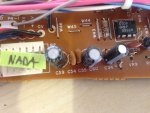
Thanks mdainsd! Ten four on the orientation. As for the schematics, would a guy like me even need to look at them. Seems to me if I have a parts list and if the circuit board has the corresponding numbers on them (C59) like this... photo.JPG
 
If I were you, Marigoldkh, I would just leave opamps be. Get the board recapped and live with it for awhile. See if you are faced with sonic limitations and THEN explore the idea of those "upgrades" and ask serious questions about whether or not they will actually help you meet your needs. Putting a different chip in is NOT a silver bullet. Its not going to work miracles. There is so much more at play in the circuit design and circuit path and typically at BEST "improvements" are subtle, and at worst if not done right quality suffers.

OK cool, I've recorded and mixed on the 520 for a couple of years now and I can honestly say it does sound dark or brown. At first I didn't get why people were saying that...I do now. I'll take your advise though and let them be.
 
Yup.
There's no reason to try and compare the schematic and the board as far as how parts are laid out. They are not going to be the same. The parts and how they relate to each other, yes, but the schematic is not drawn to represent the layout of the parts on the board. That's what the PCB layout is for on pages 138~140.

OK I see the difference between a schematic and the PCB layout. I'll probably never need to look at the schematic.
 
Thanks mdainsd! Ten four on the orientation. As for the schematics, would a guy like me even need to look at them. Seems to me if I have a parts list and if the circuit board has the corresponding numbers on them (C59) like this... View attachment 86796

I don't use the schematics as a resource for recapping except as a cross-reference with the actual assembly and the parts list to confirm values. I've already done that for the M-520 and there aren't any discrepancies on the input boards.

The only other time I use the schematics related to recapping is if I'm looking for opportunities for modifications on the values, but Teac is generally spot on.
 
OK cool, I've recorded and mixed on the 520 for a couple of years now and I can honestly say it does sound dark or brown. At first I didn't get why people were saying that...I do now. I'll take your advise though and let them be.

Well that's some good information. Its good you have some significant experience with the mixer, and it means something when your ears tell you something that is also corroborated by other listeners. I still say one step at a time.

Electrolytic capacitors are a compromise. They are cheap and relatively small for a given capacitance compared to, say, a film cap. Film caps get HUGE and $$$$$ even at relatively small values, but have better HF specifications. The larger the value the better LF performance at the sake of HF performance with an electrolytic cap.

That's where the convention of adding a small value film cap in parallel with an electrolytic cap comes in...lets the high frequencies through, but there is debate about complexities that may occur with these two caps in parallel because neither of them are linear in their response or the same as each other.

Compared to the original caps on your input boards, new parts today have lower ESR (electrical series resistance) which translates to better HF performance. So my practice has been to just put new good quality low ESR hi temp caps in and call it good...and I like using the Nichicon KTs for this as they are affordable, readily available, and designed with audio use in mind.

SO...

You might experience some HF performance improvement just with the recap.

YMMV

Then if you *want* to go for more you can try some opamp upgrades but you'll generally want to bypass the power rails at each upgraded opamp with a small value ceramic cap, and you'll want to be mindful of the drive potential of the stock part and make sure the new part can meet that minimum. IIRC the M-500 input boards use a 4556 as the fader booster which has really high output potential and I think I and another member really never got to the point where we had a suggested upgrade part ascertained because nothing really has that high an output. So the question was "how much of the 4556 drive is actually needed?" And we never experimented.

Anyway, one thing at a time is wise advice that has been beaten into my head by people with rights to do that sort of beating.
 
Still waiting for that cap list.... :eatpopcorn:

Pssst! Don't forget about the power supply...it has *everything* to do with the audio performance of your mixer!!!
 
I knew you needed 7 of those 10uF/16V caps because I counted them up just like you did. Notice C36 is only installed on board types "b" and "c" (look at your list you put up several posts ago). Now look at the chart at the bottom of page 197. Notice C36 is only installed on board types "b" and "c" which are channels 3 and 4 respectively. The rest of the input boards in the M-512/520 only have 6 of those 10uF/16V caps. Make sense? That's why you need to tell me which channels you are planning on recapping because there are a number of caps only installed on boards "b" and "c", but not the others.

And your aggregate list of caps...recheck your count for the 22uF/25V. And what happened to the rest of the caps on the list?? Your list in post #465 has 26 caps, but your aggregate list in post #467 only has 18 caps...?

SO...

  • Back to the drawing board somewhat on your aggregate list...
  • STILL be thinking about the power supply
  • TELL ME WHAT CHANNELS YOU ARE RECAPPING

Your turn. :)
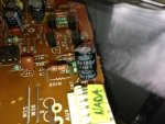
When you say board types "B" and "C" are they labeled "A B C D" a module? The "E F G" confuses me (pg 197). Not sure that's relevant at this point but just tying to make sense of what I'm looking at. looking at the actual circuit board is what makes the most sense to me. I see the values are labeled on the caps themselves. Looking at this "parts" circuit board I dissembled, looks like I need
1. 50v 1uf
2. 16v 10uf x5
3. 25v 47uf x5
4. 25v 22uf x6
5. 16v 100uf x2
6. 16v 470 uf
7. 50v 22uf x2

22 total caps & 7 different kinds for input PCB 137

Not sure if that's right or not, but nonetheless, I will correct my list. Did you want all the caps listed not just the groups? Power supply... since this is my first venture into any kind of work like this, I am more comfortable practicing on something first...i.e. the parts board I have. If I had a parts power supply, I would def start with that or if I have performed work like this in the past and was comfortable with the process, I would start with the power supply. As for the channels, pretty sure I mentioned it, but I will be starting out with 1-4.
pardon my late responses, working 2 jobs etc. Thanks for your patience, I really appreciate all the help.

I will correct my list soon
-Kenny


photo.JPG
 
Wow such great info! I trust you, I bet I'll hear a big difference with the recap.
If I hear no difference, that might mean this process has made me mad, or maybe I'll get nuts and try the op amp upgrade.
 
Alright lets see if I got this right...

10UF - 16V [C14, C20, C25, C33, C34, C36, C48]
22UF - 25V [C12, C13, C19, C21, C22, C23, C35]
47UF - 25V [C10, C11, C15, C59, C60]
22UF - 50V [C1, C2]
470UF - 16V [C7]
100UF - 10V [C16]
1UF - 50V [C24]
100UF - 16V [C46, C47]
:guitar:

I explained in a previous post why I'm starting with module 1-4, but I'm not forgetting, maybe after I complete 1 module I'll look at the internal PS.
 
I understand now why you're staying away from the power supply recap. that sounds wise.

The input boards are not labeled "A", "B" etc. You have to know which channel they are and that tells you which letter designator they are. The "A" boards are channels 1 & 2. "B" is channel 3. "C" is channel 4. "D~G" are all the same as far as electrolytic caps go (but there are some differences related to *other* component types because of some of the routing feature differences on the different channels...that's why there are more different types even though the electrolytic caps are the same). The reason channels 1~4 are different is because of the instrument preamps on channels 1 & 2, and the phono preamps on channels 3 & 4. That's why they are different.

Your list you posted in your last post is *close*...

Referring to the parts list on page 142 and counting manually:

  • "A" channels (channels 1 & 2) have 21 electrolytic caps mounted (this count includes all "Elec." caps EXCEPT those denoted as for "(B, C)" as well as those that say "(All except A)".
  • "B" and "C" channels (channels 3 & 4 respectively) have 26 electrolytic caps mounted ("B" and "C" boards have ALL the electrolytic caps mounted).
  • All other channels have 23 caps mounted (this count EXcludes caps denoted as "(B, C)", and INcludes caps denoted as "(All except A)".


SO...still a little work to do because you counted 22 caps and that's not possible according to the service manual. Re-check and let me know.

Then we'll know which board you are using as a guinea pig and I'll know what shopping list to make for ya.
 
Lettering-
So each channel 1-20 or 1-12 in my case has a letter assigned to it? And this letter corresponds to info in the manual that says what type of caps to use? Won't it be obvious by just counting the caps and referring to your 3 bullet points?

Are you saying my guinea pig count was off and my post #478 was correct?
I recounted my guinea pig and counted 23 caps, which means it must be a "all other channels" module.
1UF 50V
10UF 16V (all excpt A)...x6
22UF 25V (b, c)............x6
47UF 25V.....................x5
100UF 16V...................x2
470UF 16V
22UF 50V....................x2


Another thing I'm confused about is you say,
"(this count EXcludes caps denoted as "(B, C)", and INcludes caps denoted as "(All except A)"."
So obviously 22UF 25V is noted as "(b,c). What does that mean? That cap is on the circuit board not once but 6 times! Has my guinea pig been recapped wrong?

hold the boat...looking at the board it has a section that says "phono. Line, AMP" In this section there are missing caps... ( c16, c17, c18, c19) I'm pretty sure that makes my guinea pig a B & C channel. Which makes sense because you say,
"("B" and "C" boards have ALL the electrolytic caps mounted)."
However 23 plus 4 = 27...

Not that any of this is too important because I'm just practicing on this guinea pig. I thought the caps looked kinda new...they say "marun" or something like that...so tiny.
It's good to understand what I'm working with either way. I figured If I do a good job on my guinea pig it could be a backup module.

Is the parts link your providing me gonna be for the entire console? :-) the 512 should be like the 520 (-) 8 channels.

Also, for future recap jobs, is it possible without a manual to look up what caps are on the board and order new caps with the correct values? If we were not talking that's probably what I would have done. :cool:

Again, thanks for the guidance, much appreciated!
 
Back
Top