Royer Mod starting

Blue Jinn

Rider of the ARPocalypse
OK,

This is an oldie but a goodie. Got myself a MXL2001, not working, had some BigUgly version RoyerMod PCB's fabbed and now embarking on this. First time to do a microphone, so I'm going cheaper on this one. Got the PCB, got a 5840. The PCB is for the "BigUgly Mod" which is a mod of the Royer mod to use dual diaprhagm capsules, but the PCB can be used for a conventional Royer mod as well. Bought a $10 KCM transformer from Ebay,. Whole thing shouldn't set me back too much. Will post updates and some pix as this progresses (which knowing me will be slow, so your patience if you are actually interested is appreciated.)

I have extra PCB's too if anyone is interested:

https://homerecording.com/bbs/speci...quipment/royermod-g7-pcbs-331458/#post3740496
 
Last edited:
Yeah I want to see this happening Blue Jinn.
I have a few 2001 ..... maybe I'll purchase the PCB's from ya!
 
Cool. I have a bunch of parts at home, but I've going to just do a Mouser order to make it simpler this time. That way I don't have to whip out the resistor cheater card, and sift through a drawer full of em. Contemplating the capacitor at the moment.... The PCB has a nice tube outline. I could actually bend the leads on the tube and not have them short, but I'll get some kind of insulation on there anyway.
 
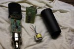
Took apart the MXL2001 (I didn't test it first, I bought it "not working" so don't know what hte problem was with it. Hopefully not capsule....)

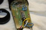
Comes apart pretty easy. Set aside the circuit boards to desolder and reuse the 1Gig resistors on the G7.

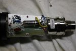
Some of the resistors I got were a little old and pretty big. The capacitors had to be soldered on the back of the board also due to size. It looks like one of the solder joints may brush up agianst the railing. It connects to ground, so that shouldn't be a problem. Otherwise, the board fits fine. The board has a nice round pattern for hte tube, so there aren't any shorts apparent even w/o any shrink tubing on the tube. Transformer fits nicely where the old one was. Not sure the specs on the old one, if it can be reused for something else. I think it is 2:1. If 1:1 could maybe have used on the PRR VariMu.

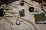
The brass screw on the XLR stripped right away and I had to drill it out. Don't have all the parts yet, so completed what I could. Pix below:
Parts:

smallIMG_3299.jpg

Progress:

smallIMG_3301.jpg

Need some caps etc for the PSU, as well as a transformer. I have a 120-120:12v-12v but it is only 10VA, I don't think I can use one of the 120v windings as a secondary. I have an email into Mableaudio for a custom toroid, see how much that runs.
 
Last edited:
Disassembly of the 2001 is fairly easy and straightforward. The bottom cap unscrews, followed by a larger piece that unscrews. The two boards screw to the side rails with little philips screws. six more screws on the transformer & xlr plug housing. The XLR plug should unscrew, mine wouldn't, and I had to drill it. I have another XLR plug with a proper screw and confirmed it fit fine, but need to get a 5 or 7 pin one. I took off the headbasket to take a look at the capsule, and could not get one of those screws to fit again. I'm sure it will hold together OK with one of them kinda loose, so need to be careful the next time.
 
The new transformer (KCM from Ebay) is slightly larger then the stock transformer. So I needed to use a power drill and notch out the bottom case just a bit so it would fit. It is a pretty tight fit, and the bell covering it doesnt' line up exactly. With a little patience i could proabablyt make it fit, but it lines up enough to get one railing bolted to it, which is sufficient to keep it in place. It is also a tight fit to run teh extra wires from the 5 pin XLR up and through, but I managed to do it.

Got some five pin XLR's and cable from Vafamsound off Ebay, (Local so shipping was quick) Waiting on a Mouser order for the last components. If that comes today, can finish up and test over the weekend!
 
Finished up the boards, put mike together. PSU is complete, but not in a case. Damn, those 220uF caps hold a charge a long time. 1K resistor comes in handy.... Want to optest before drilling anymore....
 
No, but it barked when I set the board down in the PC PSU case I'm going to use.... Funny too, I was getting 100v exactly from the B+ (unloaded) after that it will only go to 99!

I need to move a capacitor tonight on the mic board and then optest.
 
Optest was initially unsat, I had a cap in the wrong place (no ac ground path for the capsule.) Moved the cap. No problem. Note that BigUgly's boards are apparenlty intended to have solder posts for the capsule leads, I don't have any, so I had to improvise with a nut and screw for that capacitor. No hum even with the shield ungrounded, (and the PSU for that matter,) optest sat when i moved the cap. Mine is a bit noisy, (hiss) but the mic itself is pretty hot, so I don't think the noise is going to be a factor. Have to drill a few holes and install the PSU (recylced computer PSU case.) I don't have a stock 2001, so no basis for before/after comparison at the moment.
 
Well, I ran the capsule leads straight to the board, and the mic works but is pretty noisy, (and rather brittle sounding.) So, I'm going to pull one of the teflon posts off hte old 2001 board, and wire the +lead from the capsule to that and see if htat helps. I'm also, going to move the ground side cap, and maybe see if a big resistor helps. I even have a 2 gig.
 
I need to clean the flux from the board too. This and the insulator should help with the noise problem. Note I didn't use the teflon standoffs BigUgly recommends. I will try that next time!
 
Unsoldered the capsule hot lead, and put one of the MXL2001 teflon posts and soldered to that. Also, cleaned some of the flux with isopropyl and a cotton swab. (toothbrush probably would have been better, but I was pressed for time.) It is amazing the difference those two seemingly minor things made in the noise level. Still a little bit of noise, but the mic is pretty hot, and the bottom end much better, and I've read recommendations to "Burn in" the tube as well, (which gets pretty warm considering its size.)

More cleaning, and maybe some insulation on the tube leads could cut the noise even more, but I don't think the noise level is really a problem at this point.

So, lesson learned, keep the teflon from the donor mic and use them. Also, clean flux as you go along.

--edit, re-read the actual Royer article today, and the grid lead from the capsule is spliced directly to the tube lead, "feeding through" the PCB the insulated tube lead and splicing in mid air. (PRR mentioned splicing thus in answering my question re: the insulators. )
 
Last edited:
Here are some pictures. I didn't take a lot of in progress ones though.

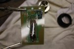
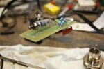
This is the finished mic circuit, with the cap moved where it should be and the teflon post for the capsule lead: Note to self, 1/4 watt resistors are probably OK, and would surely fit nicer. Also, I could and probably should have connected the capsule directly to the tube grid lead in mid air, bypassing the board altogether. I'm thinking of doing this circuit with a 6AK5 instead of a 5840, and I could run it straight to the tube socket in that case.

As indicated before, BigUgly's boards are for a G7 type circuit, but I used for the stock RoyerMod.

IMG_3350.JPG

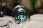
Switchcraft A5M. Per tapeop, these fit. Per Tapeop the Neutrick don't, note you must have one like this with a screw, not the snap fit kind found e.g. on the MXL tube mics cable.

IMG_3308.JPG

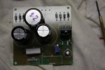
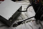
Partially complete PSU board, and recycled PC PSU case. Note the big Switchcraft XLR fit nicely in the hole for the PC Pwr Cable, with a few sheet metal screws. The XLR came from one of those Shure mixers that for some bizarre reason has male connectors instead of female on the inputs.

IMG_3310.JPG

I don't have a chassis punch, nor did I have any chassis mount 5pin female, so hard wired the cable

IMG_3351.JPG

I used a 9v and a 12v wired backwards and BigUgly's PSU circuit. I used his PSU stock, with a 330ohm resistor, and got 99vdc on the B+ side. (measured w/o mic plugged in)


Couple of progess pics:

IMG_3304.JPG

IMG_3303.JPG

Note to self, don't connect the capsule lead directly to the board:

IMG_3305.JPG

Also, it helped in my case to let the mic run for a couple of hours. I've read pro/con about "tube burn in" and "allowing capacitors to expand" or some such. But in this case a couple hours on seemed to settle everything nicely, so there must be something to that "burn in" concept.
 
Last edited:
Back
Top