Powerless Mixingboard

adwaz

New member
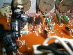
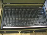
I bought this mixingboard a couple years back and it seemed like a killer deal. I guess I forgot the "If it sounds to good to be true, It probably is". It's a nice looking board with a road case, but didn't include the power supply.
After 2 years of googling and searching, I have come up with nothing. This board never existed.......Maybe If I could read Korean, I might be able to find out something.

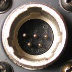
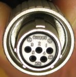
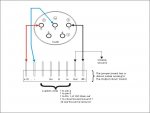
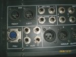
Has anyone out there ever heard of a Samick M24 mixer? If so, IYHO, is it worth trying to put together a powersupply for it. If so, where in the world would I start without a schematic with voltages?
 

Attachments

  • SamickM24.jpg
    SamickM24.jpg
    28.1 KB · Views: 124
Ok, mshilarious,
I have been reading these forums long enough to know that I am lucky to have you as a source of information. Sorry It took so long to get this pic. I had to run to the studio and yank the board out of storage to get you ,what I think you are looking for, The 5-pin din picture of the power supply hook up. Let me know if this is enough. I do realize that this board would make a great BOAT anchor, since it is very, very heavy.......Let me know if you need more info..........

ADwaz
 

Attachments

  • Samickrear2.jpg
    Samickrear2.jpg
    25.6 KB · Views: 114
Is that a 5-pin DIN? I thought MIDI cables used DIN, and that is different. Anyway, there is no hints on the back panel, so if a schemo or service manual is nowhere to be found, you're going to have to open her up.

You might ask on prodigy-pro just to see if someone is familiar with the board. This is kinda a baby DIY board compared with prodigy.

I would guess the pins are ground, +/- rails, +48V phantom, and maybe a low-voltage rail for meters. Wild guess though, and that doesn't tell us how much voltage on the rails, or which pin is which, etc. Also the power supply capacity, but that's easy enough to overengineer.

I might swap out that connector for a 5 pin XLR, just because I like XLRs better, they are cheap, they are latching, and I know what they are . . .
 
5 pin din, but a tad larger than My 12 channel A,H and B board....I would have tried it if it actually hooked up. Don't give up on me mshilarious, I know you can do it! Isn't it funny that no one has ever heard of a Samick 24 channel board? I will open her up and hopefully there will be a schematic on the inside of the console. I hope! This is a 2-man board. Meaning, it takes two people to hold it so you can open it up. Worst case senerio......We can piece out the channel electronics for the "build your own analog mixer" thread......Way to much of a nubie to know about prodigy-pro, but will try and check there.....
Thanks for your help!
 
Wow, need to spend a while on prodigy-pro before i feel comfortable posting there.
I'll do it.......
Thanks!
 
I'm sure you've found the company website, but here's contact info for various countries including the US:
http://www.samick.co.kr/eng/about/global.php

Have you tried contacting them? (though it looks grim)

And here's a newer version of the M24 (Korean site only):
http://www.samick.co.kr/eng/products/products_view.php?pd_idx=72&ct_code=020002

While it's updated from yours, there might be some documentation to be found from the company.
The contact link is broken (as is half the site), but here's the page:
http://www.samick.co.kr/eng/customer/contact.php

And here on the US site:
http://www.smcmusic.com/general_contact.html
or
http://www.smcpianos.com/contact.htm

You might ask if they have authorized service centers in any shape or form. If so, they could possibly help you as they would presumably have access to technical info.

Side note: It's exactly the same connector, though gender-opposite, as on my late 80's, English-made Soundcraft 200B. Same pin arrangement and keys around the inside of the barrel (which is threaded and quite secure).

Maybe you'll get lucky and find some info inside chassis... well, probably not. Good luck.
 
That connector is neither a 5-pin DIN nor 5-pin mini-DIN. The pin layout is completely wrong. This has three across followed by two across. With a 5-pin din, the pins are either arranged in an arc (two variants of this exist) or in a square with the fifth pin in the center. A 5-pin mini-DIN... well, it looks like this:

http://shop.vetcosurplus.com/catalo...=6590&osCsid=072507367ef99d357201bd2fbd2ddd41

I guess it could be an 8-pin mini-DIN with two pins removed, but it really doesn't look as small as a mini-DIN....

There's a narrow possibility it might be a CBC5RX. I can't find a photo of one to know for sure.

This connector definitely does not conform to any connector standards used in the last two decades or so. Thus, my gut says your odds of finding this connector are precisely the same as your odds of finding a power supply for this unit---I'm not convinced this connector exists on any other device in existence, or if it does, they're all antiques. :)

I agree with MsHilarious. Get yourself a 5-pin XLR connector and ditch the connector that's in there currently.
 
Wow, Good job whale, I actually feel a bit of hope after seeing the "New and Improved" M24. Still have the same problem with the broken links. I actually sent an e-mail to the Korean site probably a year ago. Never got a reply.

also, Mshilarius and dgatwood, please forgive my ignorance. Calling that connector a "DIN" was the closest thing I could compare it to. I don't see a problem changing it out to a more conventional connector (5-pin XLR connector) Great Idea.

I will keep you all posted on what I find on the inside.
Thanks again to all!
 
It kind of looks like one of those weird variations on XLR plugs that they sometimes use for lighting equipment.

This really is a minor problem to sort out for a technician. What kind of plug is on there really is of no consequince. Any other chasis can be put in there and a proper power supply hooked up. The only problem is to find a good technician that won't use your ignorance (not meant in a bad way) to rip you off.

Like I said in another post, technicians at charity shops have buckets full of power supplies. If he's a nice guy (and people at charity shops often are) he might see about that plug for you too. Give him a nice tip for the shop of course.
 
Well, when you feel like opening the case, the first step is to trace each lead until you find a filter capacitor. Then you note that capacitor's rating--the voltage will have to be less than that number! And if you find a capacitor connected "backwards" to ground from a trace, that's a negative voltage supply. If the console uses IC opamps, trace their V+ and V- pins until you get to a pin. Now you know which pins are +/- supply voltage.

From the XLR input pins, look for their phantom supply resistors--these are probably 1/2W, which makes them a little bigger than most other resistors that will be in there, and they will be in pairs close to the mic inputs. Follow them back to a pin, or if there's a global phantom switch, trace that back to a pin. That's your +48V pin (assuming the board has that!)

That would just leave the mystery pin . . . follow it and see where it goes!

Note the opamp they use, and look up its datasheet. That will tell you its maximum power supply voltage, probably 36V or 40V. If it's 36V, I would go with +/-15V, and 40V I would use +/-18V, unless the filter caps are only 16V rated.

Finally, count up all the opamps you can find. If they are dual opamps, give each 10mA, single opamps, 5mA. But check the datasheet's rating for quiescent current, in case it's more than that! OK, now you have a total quiescent current draw, with a little bit of cushion. Add at least 50% to that number. That is your power supply requirement.

If there's a bunch of discrete transistors instead, that's going to complicate things quite a bit :o

Phantom is similar: 24 inputs * 14mA each is 336mA. I'd do 500mA, and make sure the phantom supply resistance is low enough so the voltage doesn't droop below 44V when you draw 240mA. Lessee, that's 4V / 240mA = 17 ohms.
 
Found the connector by enlarging photos of the connector on my Soundcraft.
Two manufacturers:
JAE
Hirose

Can still find the connectors on JAE's site. Can't make a URL to take you to the page, but here's what you need to find it:
http://jae-connector.com/en/type_en.cfm
- Click under Type Search, I/O Circular
- Under Mating Combination, Choose Type 1, select 5 pins
- Click the SRCN Series link at the bottom
- under the photo, click Product List/Drawing

You get 6 hits yielding both genders for the chassis and for the plug.

The part numbers are:
SRCN2A13-5P
SRCN2A13-5PX
SRCN2A13-5S
SRCN6A13-5P
SRCN6A13-5S
SRCN6A13-5SX

I don't connect and disconnect mine at all regularly, but it's a solid connector with a sleeve that threads onto the chassis-side's barrel.

Almost certainly a useless comparison, but my PSU pin-out is:
1- ground
2- ground
3- +48V
4- -17V
5- +17V

Of course this is worthless without determining the PSU's requirements, but mshilarious's instructions sound like the right way to go for that.
 

Attachments

  • 200b_PSU1.jpg
    200b_PSU1.jpg
    49.7 KB · Views: 97
  • 200b_PSU2.jpg
    200b_PSU2.jpg
    61.2 KB · Views: 92
As always, thanks for all your help.

Oh,
find a good technician that won't use your ignorance (not meant in a bad way) to rip you off.

No offense taken in any way, shape, or form!

MsHilarious,
I have opened up the board (very nice modular design)
Found some Interesting info. I do better with pictures, so here is a diagram of what I found. Hope this isn't too big.......

Let me know if this info gives you more insight.
I will follow your current advice on calculating Amperage requirements, If I can.....
 

Attachments

  • Samick pwr.jpg
    Samick pwr.jpg
    28.7 KB · Views: 99
The ground scheme seems normal to me--all pin 1s terminated straight to ground, the analog ground on the board terminated separately.

All that remains now is to count the opamps and determine their current requirement. I'm going to guess you'll need 2A on each rail, which unfortunately will exclude the kits from JLM or Fivefish . . . maybe somebody knows of something else out there so you don't have to build from scratch . . .
 
mshilarious, I would vote for Over engineering....2-amp. Since I don't know the difference from an op-amp and any other IC. I am shure that you are getting tired of talking to "Brain Stems" like me whom, after reading these forums for months, still don't know as much as you have forgotten. Having to educate anybody before you can advise them, must drive you crazy. (comment required)

The board is very easy to access. Each of the 24 channel inputs(I don't know what you call it)...is just a 2 screw removal(1-top, 1-Bottom). The entire output section is removable with just 4 screws. The Whole Back section (Inputs and out puts) is very easy to access. Not alot of cable to pull them out far. Everything is "Hand solderd. No Korean on the cuircuit boards, all english. (I couldn't believe it)

Any ways, where do we go from here? We have the pin-out on the Power Supply connector. (we can certainly change the connector) Lets assume that +/-15 @2 amp and +/-48 @ 2 amp is OK? Now we have to educate adwaz on powersupply design.
OMG.....

I will let you think on this for a while.....
I will always read, read, read on the Homerecording forums.
I have learned a ton here........Thanks
 
Post a picture of one of the channel boards so that we can read the labels on the chips. Most of them are probably opamps.

You shouldn't need 2A for phantom, see above. As for a power supply schemo, I will look around. It's not complicated, but most of what you will find uses regulator ICs that are 1A or 1.5A rated. So instead, you have to build your own regulator circuit and use a power transistor with a higher rating. It's easier than it sounds, but still tricky without a PCB kit . . .
 
Curcuit board Pic

Here is a picture of the only part of 1 input channel board that has any opamp looking chips. Sort of hard to read in the pic but both (2) say:

0720
JRC
10218
(I could not find a Data sheet on these)

There are 2 transistors at each end of the board (2 groups of two) I cannot see well enough to read what they say. They are the 3-leg type.
Second pic shows 1 of the 2 groups of 2. Not a very good pic.

I have more info and several more questions.
I will post again shortly with the rest of the story.......
 

Attachments

  • CBC.jpg
    CBC.jpg
    13.1 KB · Views: 80
  • CBL.jpg
    CBL.jpg
    14.2 KB · Views: 81
Whale,
I am having a problem with picking out the correct conector.
You certainly found the correct web-site, but not knowing what exactly to look for, I hesitate to order anything. I just want to get this right. I need the Male end of a Circular-5pin threaded connector. Solder connection is fine. I'm sure I need a diameter measurment.
Could you tell me what you would measure, look for, etc..... You must know a lot more than I. There are just too many choices when I follow your instructions and I don't know what to look for.
Thanks for all your help.

Edit: After spending quite some time on this connector. I believe I have finally figured it out. SRCN6A13-5P is what I need .
Think I will wait till after the holidays to order. Thanks again for your help Whale Bone!
What a great connector locator web site. (once you get the hang of it)
 
Last edited:
Back
Top