INA217 Build... a problem

NeveSSL

New member
Hi all!

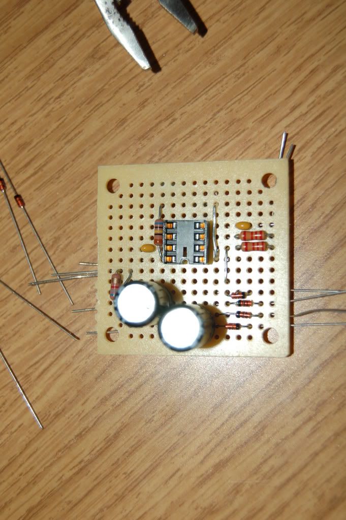
For my final class of college, I'm building an INA217 preamp based just on the schematic in the data sheet and playing around with it. I'm also comparing it to some other pres and writing about a 26p report on it, but thats rather boring. :)

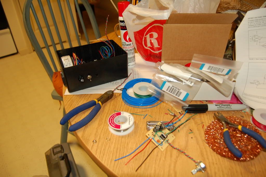
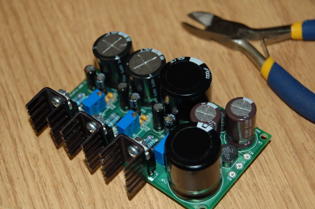
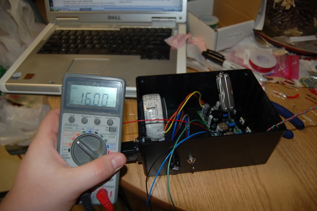
I got a power supply from FiveFishStudios (Great supply, BTW) and just put the circuit together on some small perf boards from ratshack. :)

All of my pics can be found here, but here are a few:

DSC_1009.jpg

DSC_1118.jpg

DSC_1121.jpg

DSC_1122.jpg

DSC_0984.jpg

DSC_0999.jpg

DSC_1002.jpg


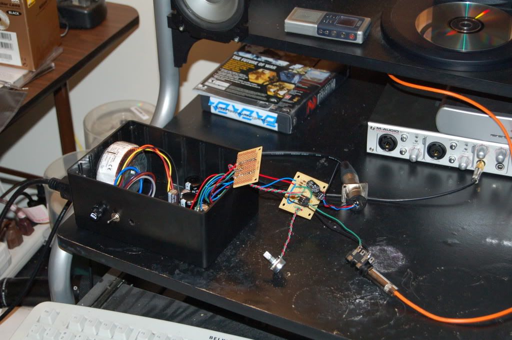
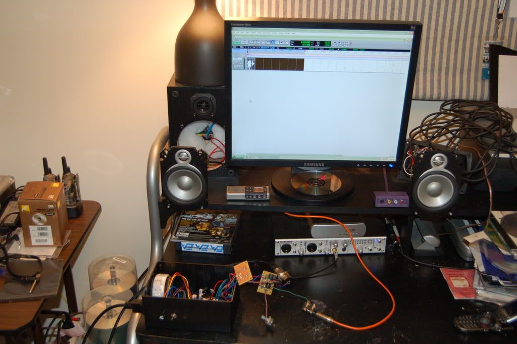
Sounds AWESOME! Very, very clean and UNBELIEVABLY quiet! I love it! Its at least a step above the pres in my M-Audio unit. Definitely usable.

Now for the problem... I can't get the gain low enough!

I'm not completely sure I understand how to setup my pot for gain. mshilarious, where are you? :)

Any help would be much appreciated.

So far I've connected a 1k pot and a 500ohm resistor (barely moved when I used the pot), a 25k pot (just for the heck of it :) ), a 1k pot with 10r resistor, 1k pot with 100r resistor, etc. Nothing really gets quiet at all... and this goes for both channels I've got and I was testing with a dynamic mic.

Any suggestions? The schematic calls for (if I'm reading it correctly) a 1.6k pot and a 8ohm resistor in series. Maybe I've got my pot hooked up wrong. Hmmm... need to go back and look... The way I have it wired is this: The 10ohm is connected to pin 1 on the INA and the wiper on the pot. One side of the pot is wired to pin 8 to finish the loop.

Hmmm... do I need the wiper and side connection connected together and then those two in series with the 10r? Maybe... I think that may be it...

Anyone have any ideas? :)

Thanks! And BTW, these things are definitely worth 4 channels at $130 or so. :)

Brandon
 
Ah man, you're making me read a datasheet on a Saturday night? OK, I'm not an instrumentation amp guy, usually I just use opamps. But Mr. Datasheet says:

Gain = 1 + 10,000/Rg

OK, the datasheet schemo does say the 1k6 pot (what the hell kinda pot value is that? And they want reverse log taper?) in series with an 8R. That gives variable gain of 7 to over 1,000, or in dB 20*log(gain), or 17 to 60dB. Actually max gain indicated would be higher than 60dB, but apparently 60dB is the limit of the chip. It shouldn't matter if you let the extra leg of the pot float or connect to the resistor.

So if 17dB is too high a minimum gain, use a larger value pot. Or you could add an input or output pad.

The question is, what you are connecting this to that 17dB of minimum gain with a dynamic is too much? If you are in doubt about the gain, get some sort of signal generator (I use a tuner), and measure VAC off the input and output. That should confirm the gain from the chip.
 
Bless you for reading the data sheet on a Saturday. :)

I agree... what kind of flipping value is 1.6k? Mouser didn't have one, at least that I could find.

The only thing I can figure is that my pot value of 1k is whats messing me up.

I'll find a source and see if I can check the gain amounts.

How are you using a tuner as a source?

Brandon
 
Bless you for reading the data sheet on a Saturday. :)

I agree... what kind of flipping value is 1.6k? Mouser didn't have one, at least that I could find.

They're not that hard to find in a Google product search, but worst comes to worst, a 1k and a ~600 ohm in series will do the job.... *shrugs*

Oh, wait... did you say 1.6k POT!?!?!?! That has to be a mistake. Either that or the schematic was drawn up by a theoretician....
 
Yep, a pot.

Maybe they did that so you would be forced to come up with your own value? :confused:

Brandon
 
10K pot

So far I've connected a 1k pot and a 500ohm resistor (barely moved when I used the pot), a 25k pot (just for the heck of it ), a 1k pot with 10r resistor, 1k pot with 100r resistor, etc. Nothing really gets quiet at all... and this goes for both channels I've got and I was testing with a dynamic mic.

Use a 10K pot (reverse log audio taper) and that should bring your minimum gain to 6dB at the max. wiper setting of 10K.

Now, if you open the connection between Rga and Rgb (or use a very large resistor), you can have 0dB gain (i.e. no gain).
 
Thanks for the reply, fivefishdiy.

Whats weird is when I open the connection (playing around with resistor and pot values hooked up to the breadboard), it gives me a lower gain, but there is still quite a bit there. And thats frustrating. In ProTools, it still hits around -30db or so just speaking loudly into it. Kinda weird. Thats what I'd love to have as my lowest, and even that seems a little hot for all the way down (keep thinking about recording guitars with a 414 or something).

Could it be a biasing thing? I didn't think I would need the offset circuit, but maybe I do.

Also, I ran my rails up to 16v instead of 15v. Not a ton of difference, but it may not hurt to pull them back down to 15 or maybe even 14v. I may try that tomorrow.

I'll dig around and see what other pot values I can find laying around. If nothing else, I need to order some phantom power mini toggles... I may do another order and grab some 10k reverse audio pots. I just hope they work! Something seems a bit off... :) We'll see!

Thanks guys!
 
Thanks for the reply, fivefishdiy.

Whats weird is when I open the connection (playing around with resistor and pot values hooked up to the breadboard), it gives me a lower gain, but there is still quite a bit there. And thats frustrating. In ProTools, it still hits around -30db or so just speaking loudly into it. Kinda weird.

Again, what are you connecting the pre to? Another gain stage? And speaking loudly into a dynamic at close range could result in -30dBV, which shouldn't translate into -30dBFS, but maybe 18dB of gain and you're there.

Could it be a biasing thing? I didn't think I would need the offset circuit, but maybe I do.

No, a DC offset just chews up your headroom. It should be minimal or zero at the input, a lot of gain can cause a small DC offset to be a larger one at the output, but that's usually only a big deal if you have a direct coupled gain stage that follows. Also, it's sloppy to leak DC out of a device. You can use the servo in the schemo, or just a humble cap. You can also measure DC offset at the output with your multimeter.

Also, I ran my rails up to 16v instead of 15v. Not a ton of difference, but it may not hurt to pull them back down to 15 or maybe even 14v. I may try that tomorrow.

Lowering the power rail doesn't reduce gain, just headroom. I guess if you lower headroom enough, you'll have less gain via clipping! But that isn't what you want ;)

But the change in headroom is rather small: 20*log(14/15) = -0.6dB
 
Use a 10K pot (reverse log audio taper) and that should bring your minimum gain to 6dB at the max. wiper setting of 10K.

Now, if you open the connection between Rga and Rgb (or use a very large resistor), you can have 0dB gain (i.e. no gain).

Hey, fivefish, I saw your new battery powered pre, you should plug that on taperssection.com in the Retail section, they love stuff like that. Just be sure to spec the phantom power current, most portable recorders with phantom can't manage more than 3mA or so, and some of them aren't 48V, so if you've got that it's a big selling point.
 
48v

Hey, fivefish, I saw your new battery powered pre, you should plug that on taperssection.com in the Retail section, they love stuff like that.

Thanks. I should get the final, final, final Prototype PCB from the factory this week. Then I'll be able to do one final testing.


Just be sure to spec the phantom power current, most portable recorders with phantom can't manage more than 3mA or so, and some of them aren't 48V, so if you've got that it's a big selling point.

Well, the chip I used for the 48V section is rated 1.5 Amp (1500mA), the inductor 0.8 Amp (800mA), so I think I can safely say yeah, it will be capable of more than 3mA :) I haven't done actual measurement yet, but from my testing, it can sufficiently power one of my power-hungry FET condenser mic. (Other condenser mics will work even at 18V phantom power, but not this FET mic... it wants 48V and sucks up power more than my other mics.)
 
Last edited:
With the INA217 the Max gain is set by the Value of the Resistor in series with the gain pot, the lower the Value the more Gain....
The Pot Value you want if you want the Gain at 1 up to 60db (with a 8r series resistor) is a 10K reverce log pot...

The problem with useing a 10K reverce log pot is that there is practicly no gain untill it is turned about 40% and it gets really touchy at the end of it"s travel...I have somewhat compensated for this by useing a 10K linear pot with a 2k2 resistor from wiper to lug createing a Fake reverce log of about 7K which gives enough minimum gain.....

These are good chips and easy to use and I have quite a collection of them now....

Cheers

PS: If you aren"t useing the DC servo curcuit you should add an output cap as the INA217 can have a few volts of DC offset at High gains....
 
Again, what are you connecting the pre to? Another gain stage? And speaking loudly into a dynamic at close range could result in -30dBV, which shouldn't translate into -30dBFS, but maybe 18dB of gain and you're there.


No, a DC offset just chews up your headroom. It should be minimal or zero at the input, a lot of gain can cause a small DC offset to be a larger one at the output, but that's usually only a big deal if you have a direct coupled gain stage that follows. Also, it's sloppy to leak DC out of a device. You can use the servo in the schemo, or just a humble cap. You can also measure DC offset at the output with your multimeter.


Lowering the power rail doesn't reduce gain, just headroom. I guess if you lower headroom enough, you'll have less gain via clipping! But that isn't what you want ;)

But the change in headroom is rather small: 20*log(14/15) = -0.6dB

Hmmm... its the line input on my FW1814. It could be another gain stage... but to be honest I'm not sure! I can't remember if I can adjust it or not in the software, but I'm thinking not.

Thanks for the replies, guys. I'm going to go see if I can dig up a 10k audio pot and go from there. :)

Also, I'll add a cap between the output and the chip. Any good suggestions on value and brand? I think it needs to be rather beefy, but I don't really know what size or what kind would be nice to my audio. :)

Brandon
 
Also, I'll add a cap between the output and the chip. Any good suggestions on value and brand? I think it needs to be rather beefy, but I don't really know what size or what kind would be nice to my audio. :)

Brandon

Nichicon PW or Panasonic FC are the usual suspects, bypassed with a small-value poly film cap if you are fastidious. As for values, I always like to assume the worst, which is somebody sending phantom into a pre from another pre (well, I guess it COULD get worse, but that is reasonably stupid enough). So I would select a 63V cap (this also helps because the cap can take 15% of its voltage rating as reverse, that's 9V, which should be way more than your DC offset) . 47uF should be plenty, although I know some people do 100uF.

Corner frequency, presuming you are feeding a 10K input impedance is:

1,000,000 / (2 * pi * 10,000 * 47uF) = less than 1Hz.

Usually you'll see that formula as 1 / (2 * pi * ohms * farads), but farads are a pain (I always miss a decimal place), so I multiply the numerator times 1M to get the denominator to uF.
 
Thanks for all of the replies, guys.

A 10k audio with 2.2k resistor across the wiper works pretty well, but goes crazy at the end of the turn. I'll try a different value over the wiper. Perhaps that will help.

I am usually able to find parts perfectly fine (and the ease of searching is why I MUCH prefer Mouser over Digikey), however I cannot for the life of me find 10k audio reverse taper pots. They just don't seem to exist on their site! :) Any suggestions would be greatly appreciated.

I found the Nichicon PWs easily. Only $0.39 for 47u/63v, too. :) Thanks for the headsup on those.

Thanks again for the replies!

Brandon
 
I can hook you up with 10K reverse log taper pots....Look here:

http://www.smallbearelec.com/Detail.bok?no=116


They are carbon but they are cheap and they actually work well but I have had about one in ten that might get a bit scratchy before it"s time.....

You can also use a stepped attenuator which would probably be the Highest quality solution, and if you make your own out of 10-12 position Lorin or Rotary switches and some 1% resistors it isn"t very expensive...You can figure out the resistors needed for a stepped attenuator by looking at the INA217 datasheet....

Cheers
 
Awesome... thanks for the reply. :)

I've ordered from ya before.

Do you have the Nichicon PWs?

Brandon
 
Hi, sorry if I gave the Impression that I actually had something to do with Smallbear ,But I don"t...when I said I could "hook you Up' I meant I knew were you could find some...Sorry

Maybe this will help in finding you some Nichicon PW....

http://octopart.com/category--Capac...--Nichicon/search?q=nichicon+pw&c=4166&w=curr

What are you planning on useing the PW"s for ?? DC Blocking or in a PSU or as bypass caps??

I personally have never used many Exotic Caps in most Projects, I have tried them but I have never really noticed an audible differance in sound useing exotic Bypass caps...For Blocking caps as in Say an ouput cap or as Phantom DC Blocking caps I have noticed a very slight differance between say a generic electrolytic and say a Nichicon Muse Bipolar but it wasn"t enough for me to justify the 10x cost increase and the difficulty if finding said exotic cap....

Good Luck

PS: I do have a couple simple INA217 PCB designs if you want to make your own PCB"s (It is very easy and quick) , the designs are all single Sided but most connections are offboard (Pots, Phantom Switch)...
 
Oh, ok. Cool deal.

Mouser has the PWs. And I'm using them as blocking caps to keep the DC from coming out of the ouput and, like mshilarious mentioned, to keep phantom from getting into the chip via the input on a (really) bad patch or something. :)

Thanks for the headsup on the PCB boards! I may take you up on that. I've got a friend who is possibly wanting me to make him one of these (just to get an edge over his 002 pres :) ).

Can you give me more details? IE, exactly whats on it and off of it?

Thanks much!

Brandon
 
Well the first INA217 Preamp PCB I designed had all of the Datasheet features like the ,DC servo ,Hot plugging protection , I also added electronicly Ballanced outputs but it made the PCB a lot larger than I wanted and after trying out a few versions without these features I decided that they had no auditory effect on the performance of the preamp so in Later versions I totally dropped the DC servo ,Hot plugging protection and electronicly ballanced outputs.....

The latest version I did was a 4 ch PCB about 6.8 in by 2.5 in that has Provisions for Phantom power and is pretty basic ,all single sided but there are a couple Jumpers....very easy to etch at home...

I also designed a 2 CH version that has provisions for Transformer ballanced inputs (Transformer ballanced output could also be added to these designs by wireing them off board) ....I used a couple Cheap Mic input transformers from a Very old Akai console and Racked them in a Box with a couple Xformer ballanced Bogen Mic preamp modules so I have 2 flavors of Xformer ballanced pre"s in the same Box....

If yer interested PM me with your e-mail and I"ll send you the PCB layout ,Stuffing guide and I"ll make a PDF for you for the offboard connections...

Cheers
 
Very cool, man.

I put the hot plugging diodes in, just because I had them. I wasn't sure if it would do much of anything, though.

What software did you use to design your PCB?

Would you mind sharing it? I've got some etchant. :)

Brandon
 
Back
Top