diy di box: transformer or dual channel opamp?

PMST

New member
Hi there, need some advice from you guys..

Bear in mind I'm falling in the trap of diy... I've never done anything before but a friend of mine (who's got some circuitry blah blah knowledge and can solder!) is willing to help...
I've read a little bit of stuff over the internet about diy di boxes and had eventually found a project that looked interesting to me ( http://web.telia.com/~u31617586/#active DI-box my work horse from 1975 )
I found that buying the transformer required from the UK would cost me about 46£ including shipping (the equivalent of about 66 dollars, not too bad.. and I live in EU so no annoying importing taxes)...
Well, that would be the major expense, and it looks like I'd end up with a good di box...

Now, I've heard that you can do without the transformer and use a dual channel JFET op-amp to make a phantom powered di box instead..
well, considering that for example a 10 pcs lot of TL072CP by texas instrument would cost like 10 dollars including shipping from the US (taxes would be like 2 dollars)... it starts to look interesting...
I mean, it would be way waay cheaper, some say there are even advantages using the opamp active di configuration vs the transformer passive di...
Now I don't know if the TL072CP is the best option out there (if there are better op amps for this particular purpose, I'd be glad if you named them), but if I can build a decent di-box and save loads... why not?

Bear in mind that I'm quite ignorant about all this stuff, so please tell me your thoughts about it but keep it simple... and if someone here knows where I can find some schematics for an op-amp di box with ground lift switch, that would be much appreciated.
 
I moved your post here . . .

- transformers are easy to wire up, sound good, are very low noise, don't need power, will offer built-in attenuation, can give you ground isolation (not just lift), and don't have to cost $60.

- you don't need a dual opamp for a DI, a single will do. If you are using phantom, select a single opamp that uses less than 3mA (since many phantom power supplies are nonstandard).

- you can even use a single FET for a DI. You won't get as much headroom as with an opamp, but it should still be plenty for a guitar or bass.
 
sorry, I hadn't seen the DIY section...

and thanks for the answer..

since, as I said, I'm really blank about opamps and this kind of stuff...
what are the pros and cons of single over dual?
and can you give me an example of one good single opamp and a good dual one?

then, you listed some nice pros for transformers... will an opamp lack any of these compared to a transformer?

cheers
 
since, as I said, I'm really blank about opamps and this kind of stuff...
what are the pros and cons of single over dual?
and can you give me an example of one good single opamp and a good dual one?

Single is one amp, dual is two amps. You only need one channel to make a DI. With two channels, you can make an active balanced output, but you don't need that, an impedance balanced output (an extra resistor and capacitor) will work fine. Since you are using phantom power, it's much more helpful to save the power that would be required for the second amp.

Many opamps come in single and dual packages. In a single package for use with phantom power, I would look at OPA277. But good ol' TL071 works fine too.

then, you listed some nice pros for transformers... will an opamp lack any of these compared to a transformer?

Yes, all of them ;) That's why those are advantages of a transformer.
Advantages of an opamp/active balanced approach:

- potential for very high input impedance (useful for piezo pickups)
- flat response
- less low-frequency distortion (important for something like an active bass, perhaps)
- much less expensive
- much smaller

It's funny to me, but you will see people say things like use an active DI with passive pickups, and a passive DI with active pickups. As I mentioned in the active bass example, that doesn't really make much sense to me. And the piezo example, piezo pickups will suck bad through a passive DI.

For a regular ol' electric guitar, either one works fine. The active DI will have a lot more parts.

Here's a simple schemo for an active DI--you can leave out R3 for an extra-simple active DI. Build this before you start playing around with opamps, which will require many more parts.
 
Mic input tranny's for direct box?

I read in a few places that a mic input transformer wired in reverse can be used as a direct box. Any truth to this? Thanks also for the schematic, will add this to my "to do" list.
 
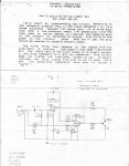
Found this real old schematic

This has to be about 30(?) years old (hey, it's vintage!) but just wanted to post this for S 'n G's. Did a search for DAAK Audio with no results, guess they went under.
 

Attachments

  • Direct box schematic.jpg
    Direct box schematic.jpg
    61 KB · Views: 2,030
This has to be about 30(?) years old (hey, it's vintage!) but just wanted to post this for S 'n G's. Did a search for DAAK Audio with no results, guess they went under.

That's the basic dual opamp for electrically balanced output. The input jack is TRS, using the ring to switch on the circuit (the plug connects ring to shield when inserted). Of course, that uses a 9V battery rather than phantom power.

There are a few things I don't like about that circuit: as it has 1/2 rail bias on its input, so will it on its output. You don't want DC at the output of your DI, that's very bad form. Probably your preamp has input capacitors, but if you switch on phantom power, you could easily destroy the DI's opamp, depending on how robust it is. So output capacitors are a must in my book, as are input and output clamping diodes.

That circuit also doesn't offer attenuation, which could be a problem for some preamps. And I think the inverting stage might be injecting a bit more noise than necessary, but it might not matter.

I read in a few places that a mic input transformer wired in reverse can be used as a direct box. Any truth to this? Thanks also for the schematic, will add this to my "to do" list.

The turns ratio is probably too low. A lot of mic input transformers are 1:4, backwards that is 4:1, which will drop signal -12dB, but only multiply impedance by 16x. I like something more on the order of 14:1, for input impedance of 200x, and attenuation of -22dB.
 
thanks for the schmatics, it looks really simple, I'll have my friend have a look at it...
the only thing... doesn't it provide with a TRS out for returning the signal to an amp?
 
... doesn't it provide with a TRS out for returning the signal to an amp?

A DI is not for connecting to an amp , a DI is for connecting it to a Mic preamp or mixer for recording... If you want to plug into an amp then just plug into an amp....


:D
 
thanks for the schmatics, it looks really simple, I'll have my friend have a look at it...
the only thing... doesn't it provide with a TRS out for returning the signal to an amp?

Sure, just take another tap off of C2. You probably don't want TRS out to the amp, just TS. That is an application where you might want ground isolation, although your amp might lift signal ground above chassis ground. If not, try a small value resistor and capacitor in series with the ground connection if you need it. If you keep the amp and preamp on the same circuit, that should minimize problems as well.
 
yeah, sorry I meant TS...

p.s. btw, I know this is a bit OT, but I asked for 2 cables to connect my monitor speakers at the shop and they gave me some TS instrument cables.. while of course the speaker inputs are balanced, and the interface outputs are TRS...
is there any potential harm for the equipment doing this or the only drawback will be the usual noise-related ones?
thanks a lot!

A DI is not for connecting to an amp , a DI is for connecting it to a Mic preamp or mixer for recording... If you want to plug into an amp then just plug into an amp....


:D

gosh, I'm not retarded (not that much at least)... a DI usually provides you with two outputs: one canon to connect to a mixer, one jack to connect to an amp...
that's because you might want to listen to your amp while recording the DIed signal (maybe you're recording your reharsal and you need to hear the bass in the room while the band plays) or you might want to mix a DIed guitar with the mic'ed cabinet...
 
yeah, sorry I meant TS...

p.s. btw, I know this is a bit OT, but I asked for 2 cables to connect my monitor speakers at the shop and they gave me some TS instrument cables.. while of course the speaker inputs are balanced, and the interface outputs are TRS...
is there any potential harm for the equipment doing this or the only drawback will be the usual noise-related ones?
thanks a lot!

Probably OK. The output is likely impedance balanced, so plugging a TS cable into it just defeats the balancing with no penalty. If it's an electrically balanced output, you might impact circuit performance by grounding a hot output, but even that is probably still no big deal. To fix that, you'd want to swap the TS connector for TRS, and just leave the ring unconnected.

Or just buy a TRS cable . . .
 
I know this is an old thread, but I was hoping I could get some info from mshilarious regarding the active DI schematic posted...possibly? I guess we'll see.:)

You posted the very simple looking circuit below with just a transistor, capacitors, and resistors. Long story short I was looking at putting this together for a DIY/learning project. I was wondering if there was any way you could give me a quick explanation of the schematic as far as what role some of the components play? Also, is this powered by phantom power I assume? Would this transistor only design be OK for recording bass?

Anyways, if you have the time to give me a quick reply I would greatly appreciate it. If you don't have time or never see the thread I understand.:)

Best Regards

attachment.php


Well I can give you a very basic explanation of the circuit that might be somewhat flawed .....

This curcuit uses a N Channel Jfet and a Phaze splitter to give a positive and negitive output ,R3 and R6 set the input impedance and Input Bias , C4 Blocks DC and create a Filter in conjunction with R3 and R6 , C2 and C3 Block DC , C1 is there to filter the PSU Voltage , and I believe the rest of the resistors (R1 R2 R4 R5) set the operateing point of the transistor ......

I Think I am fairly close with my explanation but I"m sure mshilarious will set me straight when he replies ....


Cheers
 
Good except R1/R2 feed DC (from phantom) to become the power rail.

I think I like R4/R5 better at 1k5, 1k is a bit too much for 2N5457 I think. At least with R3 in place.
 
Hey Minion and mshilarious - thanks for the info! I appreciate it.

mshilarious - I am a bit confused when you state that you like R4/R5 at "1k5" instead of 1k ohm because 1k is too much for the transistor. Do you mean that the resistance is too low, so the current is too much for the transistor? That is the only way I can understand it, as you recommended a higher resistance.

Again, thanks to both of you for the information.

Those are two ways of expressing the same thing. Ohm's Law: I = V/R. Voltage in this case is kinda sorta a fixed value. I think I used a different FET in my original design, and 1K pushes 2N5457 pretty close to its Idss (max current). So you can go with a FET that can put out more current (say 2N5458), or increase the resistance.

I mean, it might be OK, I just realized I hadn't built or simulated that exact circuit so I wasn't sure.

Alright, thanks for the info.
 
Back
Top