Toa RX-7 Update

Somnium7

Noise Criminal
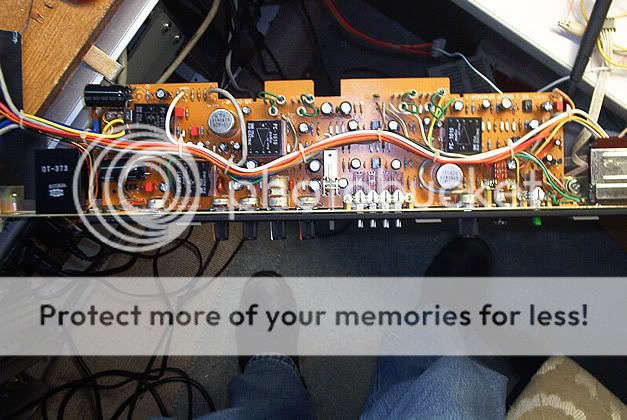
Since getting this old battleship home i have gone through it to locate any and all problems. Any board this old will have it's share of issues. Here's what I've found.
6 slightly scratchy faders - no big deal.
Echo Send 1 dead - Pretty annoying.
Group channels 1 and 3 randomly go dead or make static. - Real BAD.

As far as I can tell, the problems with the groups and the echo send are bad Line Amps, which on this console are custom made modules. After checking my resources and doing some web searches it appears that replacement modules are unobtainium. My plan as of now is to canibalize these modules from 2 of the program channels and the talkback channel. I can live without direct outputs from these. I'm still left with 6 program channels which is still more than I'll ever use. I'll also be transplanting the output transformers for each bad module since there's a good chance these caused the modules to fail in the first place.

Before I begin this surgery I'll ask here - Any ideas where to find replacement line amp modules for this console?
 
Robbing Peter to pay Paul has paid off - for now. I got all the sends and groups working with the transplants. The organ donors were the talkback module and a dual program channel module. I can live without them.

However, time keeps on ticking, ticking, ticking into the future and the future is bleak. More of these Line Amp units are gonna give up the ghost eventually. So I took one of the bad ones out back with a hammer and a screwdriver. I chipped off enough epoxy to see what's inside and to expose the traces of the little PCB holding the circuit. What I found was an opamp driving a two transistor class A amplifier. This is simple stuff.

My new project is to make brand new units to use as replacements. I'll use a really nice opamp like the AD843 and a discreet class A amp using low noise transistors. I'm already working on the design. I can have a PCB fabbed to my specs and the new units will drop right in. Since these are just output amps I don't have to worry about losing that vintage tone by improving the sound quality with better parts.

I'll see that this old monster outlives me :cool:
 
It's been a damp weekend and guess what? The BEAST doesn't like dampness! Go figure!
Anyway, all weekend long I have been fussing with the repairs and all is well now. The program modules I amputated actually still work but I can't use the outputs on them now. I got quite a scare though at one point. I had just put the talkback module back in after taking out it's line amp and powered up the console. All I heard was static. I started freaking out, thinking the group module I had just fixed was acting up again. Then it dawned on me, the talkback module also has the test tone and noise generators and sure enough I had accidently hit the button to assign noise to group 1 - DOH!

I also started replacing the meter lamps. Since no replacements could be found I had to get creative. Take a look at these pics to see my new lamps...

http://s108.photobucket.com/albums/n13/somnium7/gear/

What I did was solder some pea lamps to the old burned out bulbs. You can see in the pic with the VU meters lit the new ones are on the left and the originals are on the right. They look just as good!

There's also some before and after pics of the Line Amp units. If you look close on the broken up one you'll see the two trannys and the SIL op-amp.

Thanks to Mother's Day I didn't have time to start prototyping the design that will replace these LA units. More on that later.
 
And so begins the capping job :eek:

I am shooting pics of this as I go so others can see what work this entails. I'll post them here later on.
 
Holy Mother of God!!!! A Toa! ...and it sounds INCREDIBLE NOW!

Here's what happened over the course of today.
All BP electrolytics over 1uF in the audio paths swapped for new Nichicon bipolars. All 1uF replaced with WIMA or Metalized Poly caps. All nasty ceramic disc in the audio paths replaced with Polystyrene. Carbon resistors in critical locations replaced with 1% metal film.
Output caps for OPTs changed from 100 uF to 220uF.
All electrolytics bypassed with 1uF Metalized Poly.

Group modules 3 and 4 complete.

Why? Dude look at this! People are paying a thousand dollars or more for a preamp with 1 DOA and transformers. The Toa has 32 channels of DOAs and transformers :eek:
Not to mention the 4 groups and 8 programs.
scans034.jpg


Check out the slideshow...
http://s108.photobucket.com/albums/n13/somnium7/gear/recap/?action=view&current=5b3dce7c.pbw

So first test was the hiss test. Cranked up a recapped group module and an untouched group to max gain and raised the monitor output to max. Hiss from the recapped group was a mere fraction of the other groups.

Then after returning levels to normal conditions I put on one of the best recorded songs I know with plenty of dynamics and tonal variation (Riot Act by Elvis Costello). After A/Bing the same groups I found the untouched one to be lifeless, dull and having no depth while the recapped group had massive depth, punchyness, detail by the truckload and just amazing clarity. I am totally blown away! I had no idea this old dog had it in her.
All those wonderful little black boxes and transformers no-longer have the life choked out of them by crappy under/over-valued parts.
On one part of the PCB there are some dual opamps picking the signals off the busses, reinverting them and buffering them on to the output stage DOA. These suckers had rolloff caps in the feedback loops between 200 and 470 pF. They all got swapped for 100pF styrene to reduce the cumulative high-end deadening effect. This and the larger output caps really help this thing breathe.

It's late and many fingers are burned. I'm gonna run music through the two good groups now and salivate myself into a blissful sonic coma. :D

...and I'll dream of how it's gonna sound with all the remaining channels recapped :eek:
 
Well since at least one person is interested in this project I'll keep updating this as I go...

Now I have two groups, two programs and one channel completed. Damn it's beyond my vocabulary how impressed I am with the results.

With the HUGE increase in fidelity I began to notice that the mids are smeary sounding. So I did an experiment with the input channel I upgraded. I swapped out the original RC4558DX opamps with some OP275s I had on hand. I also chopped out the suppression caps between the inputs of the opamps while I was at it. That was the trick. Smeary mids gone.

On that input channel I upgraded all the components in the mic preamp - holy Jebus!! :eek: :eek: :eek:

I'll not be spending bucks on primo pres like I had originally planned to. These things sound amazing. I'm wondering if it can actually be any better if I change out the workhorse OP275s for something like the OPA2604. The OP275s were all I had on hand that could handle the +/-22V rails.

I've gone and placed more orders for parts despite my wife's protests. I feel kinda like I opened the hood of my mini-van to find a supercharged hemi with a throttle governor :D
 
Not that there's no interest but many, I speculate, including yours truly, have no idea what the hell you're doing!:eek: Nevertheless, it's an amazing project and I'm in awe of your knowledge and skills!!:eek::eek::D:D

----
 
With the HUGE increase in fidelity I began to notice that the mids are smeary sounding. So I did an experiment with the input channel I upgraded. I swapped out the original RC4558DX opamps with some OP275s I had on hand. I also chopped out the suppression caps between the inputs of the opamps while I was at it. That was the trick. Smeary mids gone.

What was the function of these opamps? are they in the eq circuit?

what are supression caps? do you mean the DC blocking caps? you just removed them?
 
Not that there's no interest but many, I speculate, including yours truly, have no idea what the hell you're doing!:eek: Nevertheless, it's an amazing project and I'm in awe of your knowledge and skills!!:eek::eek::D:D

----

Thanks cjacek. I tend to forget that not everybody is a hard-core geek like me :rolleyes:

What was the function of these opamps? are they in the eq circuit?

what are supression caps? do you mean the DC blocking caps? you just removed them?

The opamps I swapped are the one feeding the fader and the one after the fader, feeding the buss. With EQ and HP bypassed these are the only opamps in the signal chain.
The same opamps are in the EQ but I see no point in changing those.

DC blocking caps. I know it looks like the engineer went crazy with them but it's for good reason. I replace them with Nichicons and bypass with metal film. Then it's almost like they aren't there to my ears.

The suppression caps are the 47pF ceramic discs between the + and - inputs of the opamps. I think their purpose is to dump stray RF interference. I've started cutting them out. On some of the opamps you'll see high frequency rolloff caps in the feedback loop. They are also crappy ceramics, and I'm changing them out for 100pF polystyrene regardless of the original values. No problems with that so far and a little extra overall bandwidth can't hurt.
 
Thanks cjacek. I tend to forget that not everybody is a hard-core geek like me :rolleyes:


The opamps I swapped are the one feeding the fader and the one after the fader, feeding the buss. With EQ and HP bypassed these are the only opamps in the signal chain.
The same opamps are in the EQ but I see no point in changing those.

DC blocking caps. I know it looks like the engineer went crazy with them but it's for good reason. I replace them with Nichicons and bypass with metal film. Then it's almost like they aren't there to my ears.

The suppression caps are the 47pF ceramic discs between the + and - inputs of the opamps. I think their purpose is to dump stray RF interference. I've started cutting them out. On some of the opamps you'll see high frequency rolloff caps in the feedback loop. They are also crappy ceramics, and I'm changing them out for 100pF polystyrene regardless of the original values. No problems with that so far and a little extra overall bandwidth can't hurt.


oh cool. this is the good stuff to know that doesn't always show up on a schematic. :D are these the discete opamps or the silicon ones?
 
oh cool. this is the good stuff to know that doesn't always show up on a schematic. :D are these the discete opamps or the silicon ones?

The silicon monolithic ones. Matter of fact, to my wife's dismay, I just ordered $200 worth of opamps. :eek: :eek: :eek:

The little experiment with the OP275 on one channel was quite inspiring. :D
I ordered a handful of LME49860NA ($6 each!) for the buffer amps between the mic preamp DOA and the send outputs. The idea here is that I'll have a handful of channels where the path for the mic signal is DOA > LME49860NA with all passive parts upgraded to the best I can find. This will give me good clean mic pres to record directly from.

The rest of the monolithic opamps are being replaced with TLE2142 devices throughout the board. I chose these because the specs, price and current draw were perfect for this application. The OP275s cost a little more but they also draw much more power.

Speaking of power I opened up the power supply and found problems in there. Nothing too serious, just a bad pass transistor. Since I'm gonna have to take it apart to fix it I ordered all new capacitors for it. I'm not very happy with the design of this power supply. I'll need to build a better one later on but for now popping some caps in the sucker will certainly help.
 
Same here :p

I am watching with interest though, just don't have much to say.

Keep postin', Mike. It's - :cool::cool::cool:

Thanks Dr ZEE!

My digikey order for the opamps doesn't arrive till tomorrow and I am doing my USGS gig in DC till friday this week. I won't get to do any finger burning till I get home this weekend and sleep off the road weariness :(

One item of interest though. I have been corresponding with John Hardy about his 990C DOAs. He's had a glance at the RX-7 schematic and generously provided me with several interesting ideas for circuit mods. He also pointed out the similarities (and differences) between the channel mic preamps and his own preamp design. After studying the PCB for a channel I believe it's possible to modify the stock preamp circuit to be almost exactly the same as the M-1. Obviously, it won't be easy :rolleyes:

For now I'll just have to be content to look at schematics in my motel room at night but I am dying to try Mr. Hardy's suggestions. I guess I should also review my finances too for the possible purchase of some 990Cs :D
 
I got wickedly sidetracked with the damn power supply this weekend. Last night it got me so frustrated my wife made me turn everything off and go out to see a local Punk band with her so I could blow off steam :eek:

Anyway, the power supply is one of the most horrific designs I've seen for audio gear. I finally just gave up on fixing it and decided to give it a heart transplant. I really couldn't look at myself in the mirror if I fixed that piece of junk and then buttoned it back up. After all clean power has huge sonic benefits later on. Often the best upgrade you can perform on analog gear is to put in a better power supply.

What bugged me the most is the power supply uses noisy fixed regulator devices along with pass transistors to boost the output current. Even worse, the regulators were being biased up above their rated voltage using the old diode trick. This reduces the headroom and ripple rejection of the device severely. The end result is a power supply prone to failure, with horrid noise levels and lousy voltage regulation performance.

I chopped out the fixed regulators and their associated diodes. What remains is the rectifier/filter stage and the power pass transistor stage. Since space is limited I chose to use adjustable regulator devices which have marginally better specs then the fixed types. They keep space requirements to a minimum and allows me to retain the remaining circuitry and can cover the full voltage without resorting to any clugey hacks. Additionally there are ways to greatly improve the performance of the adjustable regulators.

What I want is to lower noise by a significant amount. To do this I scrapped the usual resistor divider method of setting the output voltage of the regulators. Instead I am using a zener diode in series with an LED to program the regulator's voltage. The benefit with this is that it reduces the impedance the regulator's built-in error-amp sees by several orders of magnitude. Since the impedance is very low the error-amp has better noise rejection and faster performance. So there's two birds with one stone. On top of that the combination of a zener diode and an LED for programming the voltage is very nice because the temperature coefficients of these two devices cancel each other out. Now regulation is improved with temperature compensation. A nice thing considering how hot things can get inside the power supply. To top it all off I added a bypass capacitor to the voltage adjustment pin on the regulators which also reduces noise gain in the error-amplifier by giving the feedback path a lower impedance. This also improves ripple rejection by another 20dBs.

My drop-in regulator cores should do wonders for the performance of all audio circuitry in the console. The console will have a little more headroom too since I programmed the cores for +/- 23V instead of the original 22V. From digging around in this machine so much already I know all the components in it can handle another two volts of supply voltage.

Yeah maybe I got a little obsessed over the power supply :rolleyes:
Maybe I should start a public access channel show called Pimp My Power Supply :D

Clean power = clean audio.
 
I got a little obsessed over the power supply

.
YES you did. :D
also, obsessed ones shake the universe, so there :)
Clean power = clean audio.
Yeah, maybe so.
Also, clean power is nothing more than a clean power. heh heh,
AND! Also 'clean audio' is NOT the goal ;)
...but we can chat&argue about that till 'the power is out' and 'the party is over' :)
My main "formular" is:
Power To The People, ...and then see what happens ;)

keep posting, very interesting project! :cool:

/respects
 
Thanks again Dr ZEE! I must admit though, after reading your post I suspect you may be inhaling a little too much solder fumes :D
 
Today I will complete the PSU job. I have finished testing my new regulator core and it seems to be alright. Here's the schematic...
Lo_Noise_Regulator.jpg


I'll shoot some pics of the installation later on.
 
Back
Top