Tascam M520 meter bridge bulb replacement

Granada

New member
I am the proud new owner of a pretty damn clean Tascam M520!

I traded this guy in one of my classes for a telecaster (mexican) and 50 bucks.

It came with 2 patch bays and a bunch of half done cabling. I just learned how to solder so I will be able to complete them, its going to a take a bit of time tho.

The one thing that i want to do that I don't know how to do it changing the meter bridge bulbs. There are 4 that are out.

I read in sweetbeats M520 story that there is some devilish cement in there somewhere and I was wondering if anyone could share on the best way to replace the bulbs.

Thanks alot
 
Start reading at post #222 in my Tascam M-520 Story thread.

There are a couple ways to go on this.

The first issue is that the proper bulbs for the VU's in the 500-series boards (and others for sure) are no longer available from Tascam. They do have bulbs, but they are the shorter variety as is found in the likes of the 38, 48 and 58 decks as well as many others.

The second issue is that the bulbs come "naked" (without the metal "fuse" caps)

The first issue is not really much of an issue except for physical appearances of the bulbs themselves, but as far as my eye can see, the luminesence is indistinguishable from the original longer bulbs.

The second issue is where you've got choices. If you're a freak like me, then you're going to find a way to get the metal caps off the old bulbs, and its not easy...

  1. desolder
  2. squeeeze the very end tip of the cap with pliers to open the crimp
  3. bust the glass on the bulb
  4. dig out the glass left in the cap as well as the cement...clean it out as good as you can. Soaking it in solvent like acetone sort of helps to break it up
  5. then I put the wire leads of the new bulb through the cleaned-up caps, drizzled a little hot-glue in there and held the caps in proper position while the glue cooled...this allowed the caps to be spaced close to the length of the original bulb even though the new bulb is shorter
  6. crimp the ends
  7. solder (and hold the cap in position again since the iron has softened up that glue again :mad:)
  8. trim the leads
  9. stick it in yer meter and enjoy the soft glow!

I'll be doing the rest of mine this way even though it is a PITA...I'm sure there is a better way but...

The other option is to just do as they did in the meters on the decks and solder the bulb in...there is no fuse-like "bulb holder" in the smaller meters. I wanted to leave the bulb holders intact in my M-520 and that is the other reason I opted to do it the hard way
 
Thanks alot


Sounds like its a little involved....:eek:

Im not a stranger to soldering but it is kind of intimidating doing it on the VU.

Im going to be Opening it up pretty soon. I am kind of nervous.

So I am going to have to order the bulbs from Tascam I presume.

Should be pretty cheap right?
 
4 bulbs are out

8 bucks a pop is a little steap, but I need that glow. I need that glow.


Actually, only 2 bulbs are out. In the m520 bulbs are wired in series 2 at a time. When one of the 2 burns out they both are dark. less money for you.

But, you should realize that if any are burning out then the others are of the same age and are just waiting for the right time to go themselves. :eek:

Some day I will need to get a nice replacement worked out.

--Ethan
 
Is there a PDF manual floating around online?

I am trying to figure out how I am going to hook up my patch bay and I have questions on alot.

Aux?

Aux out?

The whole Sub in section?

Why is there 2 outputs for the PGM faders. Are they indipendent?

How does the Talkback work. I see no outputs on the back for it
A manual would be sweet.
 
PGM Outputs

The M520 is an 8-buss board.
Each PGM (buss) output has 2 connectors in bridged mono.
They are the same signal and are not independent.
This enables the 8-buss board to support a 16-track tape deck, as
Buss-1: Track 1/9
Buss-2: Track 2/10
Buss-3: Track 3/11
etc.,...
with differentiation between low-order and high-order tracks being done with the recorder's track-arming panel.

Hope that makes sense.

/DA
 
M520 Pgm Buss

The M520 has 20 Input channels and 8 Pgm Busses.

Each Pgm Buss has two output jacks of the same signal in parallel, not stereo or independently controlled.

Each of 8 buss outputs would hook to 2 inputs each on a 16 track deck.

Pgm Buss out #1 hooks to Tape Inputs #1 and #9, because each Pgm Buss has 2 outputs.

Channeling Input signals on the M520 and assigning them to Pgm Buss 1 would feed Tape Tracks 1 and 9, the only difference or selection process between either Track 1 or Track 9, or both, is which one is set for Rec-Enable on the tape deck.

Otherwise, in buss mode the mixer feeds each of 8 buss outputs to 2 output jacks which are the same signal on each jack, so each buss output sends the same signal to 2 tape tracks simultaneously on a 16 track deck. The differentiation being which tape track is set to record enable at that particular moment.
 
How you setup your patchbay will depend entirely on your setup, and what you will need to/want to frequently access. Since, at this time, I'll be interfacing the M-520 with an 8-track deck and I have 8 channels of compression and 8 channels of parametric eq I'll probably have the SEND/RCV jacks for 8 of the 20 channels on a patchbay...no need to have the tape deck I/O on a patchbay as that can be permanently connected and switch-selectable. Not sure yet how the M-520 will be interfacing with my digital rig so it remains to be seen what goes to a patchbay and what gets permanently connected...So you see, it all depends.

How does the Talkback work. I see no outputs on the back for it

There are indeed no output jacks for the talkback mic. The routing is all internal.

The talkback mic can always be routed to the STEREO B MASTER OUT jacks...the STEREO B buss is intended to be utilized for an amp and monitor speakers in your recording room as opposed to the control room. To do this just press the T/B button just to the right of the mic, and adjust the level via the T/B pot directly above the mic.

You can also route the talkback mic to the AUX 1/2 buss, AUX 3/4 bus, or all 8 PGM busses simultaneously. To do this, flip the slate source switch (that's the one just below the the test tone frequency selector) to SLATE, and then depress whatever buss to which you want to route the talkback mic in the switchrack just below the slate source switch. The level of the talkback mic to the buss you select is determined by the SLATE level pot directly above the T/B level pot.
 
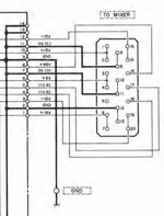
Does anyone know what the pinout is for the power supply? I downloaded a manual but it's not in there. I just built a cable and I have no meter lights but everything else seems to be working.
 
It’s in the service manual on the power supply schematic. Do you have the schematics with the manual you downloaded?
 
It’s in the service manual on the power supply schematic. Do you have the schematics with the manual you downloaded?
No I found a couple online but no pwr supply schematics. I saw someone posted it somewhere on this site but now i cant find. I need to know the gauge wire and I can make my own cable. I have all the other parts.
 
Start reading at post #222 in my Tascam M-520 Story thread.

There are a couple ways to go on this.

The first issue is that the proper bulbs for the VU's in the 500-series boards (and others for sure) are no longer available from Tascam. They do have bulbs, but they are the shorter variety as is found in the likes of the 38, 48 and 58 decks as well as many others.

The second issue is that the bulbs come "naked" (without the metal "fuse" caps)

The first issue is not really much of an issue except for physical appearances of the bulbs themselves, but as far as my eye can see, the luminesence is indistinguishable from the original longer bulbs.

The second issue is where you've got choices. If you're a freak like me, then you're going to find a way to get the metal caps off the old bulbs, and its not easy...

  1. desolder
  2. squeeeze the very end tip of the cap with pliers to open the crimp
  3. bust the glass on the bulb
  4. dig out the glass left in the cap as well as the cement...clean it out as good as you can. Soaking it in solvent like acetone sort of helps to break it up
  5. then I put the wire leads of the new bulb through the cleaned-up caps, drizzled a little hot-glue in there and held the caps in proper position while the glue cooled...this allowed the caps to be spaced close to the length of the original bulb even though the new bulb is shorter
  6. crimp the ends
  7. solder (and hold the cap in position again since the iron has softened up that glue again :mad:)
  8. trim the leads
  9. stick it in yer meter and enjoy the soft glow!

I'll be doing the rest of mine this way even though it is a PITA...I'm sure there is a better way but...

The other option is to just do as they did in the meters on the decks and solder the bulb in...there is no fuse-like "bulb holder" in the smaller meters. I wanted to leave the bulb holders intact in my M-520 and that is the other reason I opted to do it the hard way
Does anyone know where to buy the bulbs and the part number and specs? I read all I could find and didn't see anything.
 
Does anyone know where to buy the bulbs and the part number and specs? I read all I could find and didn't see anything.
Do a web search for “axial leaded lamp.” You’ll get a bunch of results. 8V lamps work well, 100-150mA. I buy mine in bulk. If you have lamps going out on an M-520 you may as well replace them all, because if some are going the rest aren’t far behind. This might seem spendy, but $30 for 20 lamps plus nominal shipping ends up being pretty cheap per lamp…will do all the meters on an M-520 with spares to boot:

https://www.jkllamps.com/DA513?pack...DiYuwmNIYZ-hRCwh8dlZG-69_S6l0iEYaAkJKEALw_wcB

I’ve used these for years in a wide range of devices from multiple manufacturers with analog VU meters…tape decks, mixers, cassette decks, etc.
 
Back
Top