Tascam M-___ Story...

sweetbeats

Reel deep thoughts...
This is the next chapter of this thread.

17 hours and counting...I will depart in my 17-year-old car to make a 2200 mile journey in less than 40 hours to retrieve the Tascam M-___ console from a friend of a friend who kindly picked it up from Shoulderpain...and by the way, give Shoulderpain some chiclets or something...He has been gracious and honorable through this whole thing. My cup runneth over. :) Wonderful guy.

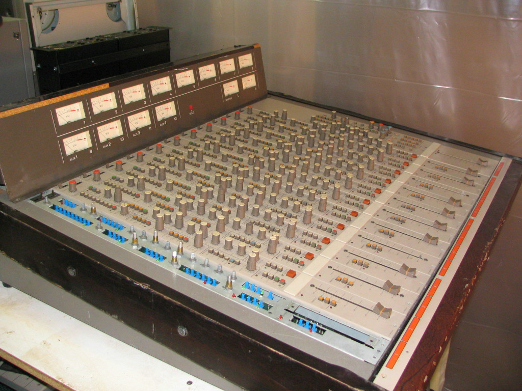
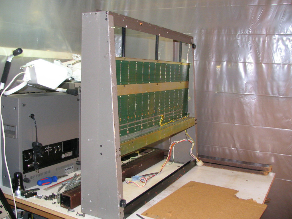
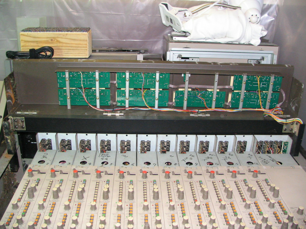
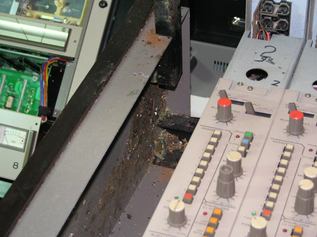
Why call it the Tascam M-___ you may ask? Well, it is nameless, but Tascam's naming convention at the time this mixer appears to have been built was 'M' for mixer, a hyphen and then a three digit number. Don't know the number so I'm putting three underscore marks.

To be continued...
 
Last edited:
We made it...

My 10-year-old son wanted to come...I explained very clearly the boring nature of the trip and the partially insane itinerary and let him decide. He still wanted to come. We had a blast, and I will never do anything quite like that again.

The trip ended up being a bit over 2300 miles, and we did it in about 64 hours including actually getting some sleep (and exploring many rest areas and gas station) one night at the Lebec Rest Area...OH! I mean, uh...no we uh...rested...yeah...we just rested there, since, ah, there's no overnight camping...yeah...uh-huh...that's how it happened...and the second at a motel on the northern California coast. The first night was comical. We made it to Burbank by midnight, got the mixer, and then drove until we couldn't anymore...that was Lebec. Then the two of us sleeping in the car with the mixer (which fit perfectly in the back of the car bhind the back seat and between the shock towers...UPS eatcher heart out)...my son across the back seat and me in the front passenger seat...ugh...memories.

We saw palm trees, redwoods, the Golden Gate, the Grapevine, a gihugic elk, Alcatraz...visited with family...getting the mixer quickly became a mere footnote of the adventure. ;)

Anyway, soon I plan on tearing the thing open and taking stills and video and putting them up. This coming week I will also see if I can extract any data off the 5.25" floppies that came with the mixer.

Until then, and since this is, at this point, a fun project that I hope we can all enjoy, are there any specific questions anybody would like me to address? I'll gladly let questions dictate what I open up first and/or what pictures and videos get produced and posted first...kind of a "What you always wanted to know about the Tascam M-___ but couldn't ask until sweetbeats got the thing home" kind of thing....:D

The Tascam M-___ in the back of the 'ru in Lebec the AM of 10/03 as we prepare for takeoff...
 

Attachments

  • IMG_7972_1_1.JPG
    IMG_7972_1_1.JPG
    61.4 KB · Views: 1,184
WOW! What a story! 2300 miles!?!?!:eek:

That mixer looks big, from what I can tell.

Yes, I have one question: I'd like to finally know what the model # is or should we keep on calling it Tascam M-___ , which, truth be told, kinda fits in light of the context of the whole story, begun by the mysterious Shoulderpain. :D

--
 
Daniel,

That's the fun part...there is no known model number. No label on the casing anywhere; the folks at Tascam don't even know what it is...they support that they built it but nobody knows about it. I'm going to try and reach Jim Finch on this one as well as seeing if there is helpful info on the disks. oooooo...mystery!
 
That's it Cory - I'm shipping my Otari 4-track to you to get refurbed. You're the only one crazy enough to do it! lol!

Seriously, looks like a nice score, congrats!


AK
 
You're the only one crazy enough to do it!

:D:D:D:D:D

Seriously..."crazy" is about all I felt at 11:00pm in the middle of a rainstorm on Hwy. 101 turning mile #1700...:eek:

My words of encouragement and assurance to my wife upon return: "I won't do that again." :D Though my son is another story...when I joked with him about an ATR60-16 I'd seen for sale in central Canada he said "Let's go!" :eek::p

I've got videos...

YouTube

YouTube

YouTube

YouTube

[EDIT]

The above videos were the first run of these overview videos captured the day I unloaded the M-__ from the car when I got it home. I later did another run of the videos using a higher quality capture device but for some reason I never posted them contemporary to their capture. I have them posted in this thread much later, and below is a link to that post. They mostly duplicate the above videos, but, again, they are better quality, and may have some clarified/corrected/enhanced information:

https://homerecording.com/bbs/general-discussions/analog-recording-and-mixing-tape-and-gear/tascam-m-___-story-270992/85/#post4491452


Here's a really big picture channel strip. It is a stitched-together panaorama, so you'll have to look past the perspective shifts and blurred edges where the individual shots join together:

Channel%20Strip%20stitch.jpg


Here is a shot looking down the meter bridge:

Meter%20Bridge.JPG


And here is a shot with the meter bridge open:

Meter%20Bridge%20Internal.JPG


Oh, and check this out...this is another kind of "hmm...I wonder" pictures regarding the possibility that this mixer was a prototype. I forgot to mention this in the corresponding video. Look at this picture and you'll see some spots that are orange in the foreground at the top and bottom (above and below the I/O panels) where the black paint has chipped off. Yeah, somebody might just have painted over the orange, but why bother on the back? And actually it is not somebody painting over the orange because there are sections with screened text on the black over the orange. Tascam used to use the orange stuff back in the day right? So I figure some of the material for the back panels may have been old stock of orange-painted sheet steel that was used to put this thing together. Also, notice that there are screw-holes along the bottom lip of the meter bridge back panel that go to nothing. Unrefined, like a prototype. Here's the picture:

Rear%20Panel.JPG


I've got more pictures, but I'll put up a couple more posts to break up and group the picture topics.
 
Last edited:
Mouse!

I think the board was sitting on its side for some time and it looks like a mouse or two was using it for a toilet and lodging. YUCK!! So far though it appears that the damage does not extend to wiring or electronics.

Mouse%20Yuck%20%231.JPG


Mouse%20Yuck%20%232.JPG


Mouse%20Yuck%20%233.JPG


Here is a general shot of the side...you can get a good idea of how chewed up the trim panels are...I'm actually glad they are there as I'd hate to think with the metal would look like were it not for these sacrificial particle board panels...

Damaged%20Side%20Panel.JPG
 
Last edited:
Shots for the geekiest

These probably won't mean much to anybody, but I took shots of the individual PCB's on the input module...as can be seen by the layout of the controls, the module features two rows of PCB's, and it is nice that there are about 6 individual PCB's on each module...if one goes bad you're not effecting the whole mess. Since I haven't disassembled the module, these pictures are really just for interest as you can only see one side of each row. Anyway...

I've made up names for each PCB based on each card's primary purpose according to the controls it supports.

Starting from the "top" of the module on the left side:

The PGM PCB

PGM%20PCB.JPG


The AUX and MONI buss PCB

AUX-MONI%20PCB.JPG


The REMOTE PCB

Remote%20PCB.JPG


And now starting from the "top" of the module on the right side:

The INPUT PCB

Input%20PCB.JPG


The EQ PCB

EQ%20PCB.JPG


The SOLO/MUTE PCB

Solo-Mute%20PCB%20B.JPG


And a straggler photo of a channel fader

Fader.JPG
 
Last edited:
Some summary thoughts/questions so far...

This mixer is really neat-o.

I think I can get it powered up. The AUX-MONI PCB is really the main PCB for the module as it has all the I/O contacts, which, by the way if you haven't watched the video of the internal tour, is really cool. This is probably a common feature in larger-scale pro consoles, but it is the first time I have run accross a channel module that literally pops out after removing two screws. Literally, you can remove any channel module on this thing in...oh...30 seconds? That is removed as in "disconnected and out of the frame". The modules plug into the mother PCB with slot type connectors reminiscent of the old ISA computer cards. Anyway, the individual slot contacts are labeled on the module including the power contacts. I haven't pulled the master module yet, and it may have some other voltages on it, but so far the channel modules require:"

  • 0VDC (x3)
  • +/-15VDC (x2)
  • +/-35VDC
  • +48VDC

The VU meter lamps may be 6VAC like the M-500 boards, and I'll probably be able to figure that out by looking at the meter PCB's.

I'm curious as to what uses the 35VDC...:confused:

Anyway, I have a spare PS-520, and so far it produces everything but the 35VDC rails. Need help figuring out how to mod the power supply to do this. Assuming that there is nothing else on the master module rail-wise, and assuming the VU lamps are 11VAC, it may actually not be as scary a project to power this thing up. I will likely retro-fit a Hirose connector for the power supply connection on the board in lieu of the Molex connector, mod the PS, make the cable and trace the rails to get the pin assignments, close my eyes and hit the power switch. :eek:

I'm still confused as to how the PGM bussing works...there is no PGM OUT jack section on the master module, just BUSS OUT jacks on each channel module. What confuses me is that there are 12 channels, and therefore 12 BUSS OUT jacks, but only 8 PGM busses. It was suggested that it may be that the 8 busses output on the BUSS OUT jacks on only channels 1 ~ 8, but it'll be interesting to confirm this.

Channel meters 9 ~ 12 are also labeled AUX 1 ~ 4 respectively, but I don't see where those are switched...it may be that the meter source select switches for channels 9 ~ 12 do this, even though they are labeled "INPUT - BUSS - MONI"...maybe this applies to channels 1 ~ 8, but channels 9 ~ 12 are really "INPUT - AUX - MONI" and only one control screen pattern was setup if it was indeed a protype board...?

The REMOTE section is totally baffling...

I realized last night as I was vedeo recording the tour of the controls that there are no AUX master controls...that's wierd considering the extensive controls in all the other areas...

I'm sure I'll have more thoughts...way too many more thoughts. :o:rolleyes:
 
Last edited:
The 5.25" floppy disks...

I forgot to mention...

I had high hopes that the 8 5.25" floppy disks that came with the mixer might have some helpful info on them...text files or even CAD data files or something, but alas, they are all blank. :eek::(

Oh well...I forge on. They are in good shape though...9/10 condition. Anybody want some nice 5.25" disks? :D:D:D
 
"I'm sure I'll have more thoughts..."

Yah-yah...my mind is spinning on this in the background...I can't stand not understanding a mixer function or a routing convention...

I may be figuring out one of my quandries, but I fear I'm even further away from understanding another one of them.

The one I may be figuring out:

In the Tour of the Controls video I mention that I am baffled by the REMOTE A & B switches next to each channel fader, as well as this section of switchracks at the bottom of the MASTER section:

attachment.php


I'm wondering if the REMOTE A & B source switches on the channel strip relate to the the GROUP A & B switchracks in the MASTER section. In other words you can convert any channel fader to a group master fader for all MIC sources, or all LINE 1 sources, or all LINE 2 sources, and you have 2 separate busses to do this, and since the 3 sources have individual TRIM controls at each channel strip, I could have a mics connected to channels 1 ~ 8, as well as 8-track tape returns connected to the LINE 2 jacks. If I was using my AUX busses for other things I could select the GROUP A input source as LINE 2, and then hit the ENABLE and 'A' switches in the REMOTE section on channel 9 or whatever and have single fader control over the tape returns while still having individual TRIM control at the channel 1 ~ 8 LINE 2 TRIM controls and still be mixing the mics on channels 1 ~ 8 and still have my AUXes free for whatever...the REMOTE feed could be routed direct to the MONItor buss via the REMOTE button in the monitor select switchrack on channel 9, or??? Its like...like...a pre-fade 3 x 12 matrix mixer, 2 x 12 of which are accessible at any one time and assignable to any 2 of the 12 channel strips with the latch of a switch...if it is something like that...that's....that's insane! :eek:

The routing flexibility of this mixer is getting kreepy...

Now the one I feel I am drifting further away from understanding:

Not only are there no AUX master controls...there aren't any AUX buss output jacks... :eek::confused:
 
How about a picture of the back side of a panel. Show the ins and outs on the channel strip.

In one video you showed that there appears to be an empty hole for a connector of some kind. That appeared to be punched for an XLR out, meaning they may have punched it for balanced out capabilities and never used that capability.
 
Tearin' in apart...

I realized in all the posts about this mixer there were no general perpective shots of the console, so here ya go:

Tascam%20M-___%20Perpective.JPG


I started pulling it all apart last night, which is actually pretty simple considering the frame assembly of the mixer. The reason I feel its gotta all come apart is to thoroughly clean up the rodent mess, and paint damaged structural parts.

Here's a pile o' channel strips:
Pile%20-o-%20Channel%20Strips.JPG


Which leaves the frame empty:
Frame%20Empty.JPG


Then off comes the meter bridge...
Meter%20Bridge%20Off.JPG


Making it easy to tip the frame up and have a look underneath:
Posterior.JPG


So far so good except for a distressing discovery when I pulled the master section...
 
Last edited:
The distressing master section discovery...

Master%20Section%20Disaster%20%231.JPG


Master%20Section%20Disaster%20%232.JPG


Master%20Section%20Disaster%20%233.JPG


Guys, I want to pull those PCB's off and clean them really well...Like scrub and sanitize while not doing damage to what may still be good. Any suggestions?

Looks to me like recapping would be a good idea :rolleyes:, and probably putting new resistors and new wiring to replace effected components. Fortunately the damage is isolated pretty much to the master fader and the PCB with the poop pile on it which carries the RIAA phono amps, headphone controls and that MONITOR switchrack that is still baffling me.
 
Last edited:
Even more thoughts and observations...

The VU Meter PCB's don't have the voltage rail labeled like the M-520 does, but the PCB looks really familiar. I'm going to see if I can cross-reference the numbers...maybe it is the same. The meters themselves are identical.

That led me to another thought...The input and master module PCB's...I wonder if they are used anywhere else in Tascam's/Teac's product line and if so if it would be possible to piece together schematics, or at least layouts...

I'm planning on pulling channel one apart and in that process I'm going to take really good pictures of both sides of each PCB and see if there are numbers. I'll put the pics and the numbers (if any) up here and maybe some of you can check your books and see what we have? At that point I will also make contact with Tascam, reference this thread and/or send them a DVD of pics and videos and see if they can get any information.

Also, any comments from you older Teac mixer owners on the frame construction or the way the channel cards go in? I was wondering if it looks at all like the series 5, 10 or 15 mixers...those all have single-channel modules right? Or even the M-600...hmm.

Overall the PCB's and general assembly look like a production model (with some exceptions) but there is still growing evidence that this was a prototype model...
 
More "prototype" evidence...

I didn't take any pictures of this yet, but there are consistent mods to some of the PCB's on the input modules, like where a scribe has been used to scrape through the foil layer to break a path, like the design wasn't final and alternatives were being tested.

Plus, as I pull this thing apart there are definitely more areas where there are superfluous screw holes, and holes that were hand-marked for drilling with a scribe like this (look at the two bigger holes on the cross-member right about in the middle of the picture):

Scribed%20Screw%20Holes%20%231.JPG


And this:

Scribed%20Screw%20Holes%20%232.JPG


Notice in the last one how there are production counter-sunk holes (with the paint still intact) and then the holes used on this mixer which were hand-marked with a scribe and appear hand-drilled...It almost looks as though the section in the above picture (which is the extruded aluminum rail that is at the front of the mixer and spans side-to-side) was pulled from the shelf and modded to fit this unit...that pattern is apparent in other places as well.
 
Last edited:
5.25" floppies

Keep in mind that those floppies could have been used in a number of various computer platforms. One doesn't know if they were used with Commodore/Amiga, Apple, IBM, OS/2, etc. There might be and inkling of hope if you can find some of those machines close by. I've got a Commodore 64, but none of the others. I need to get rid of my old computer stuff so that I can get more sound gear.:D
 
Yeah, except they literally look new, and there is no data written on them. They were pre-formatted for IBM compatible PC and they are e-m-p-t-y. :(
 
Back
Top