The grounding issues...
So I thought I'd put some detail of the grounding issues up in one post and I think the easiest way to organize this is to state the best practice and then state how that hasn't been followed in this mixer.
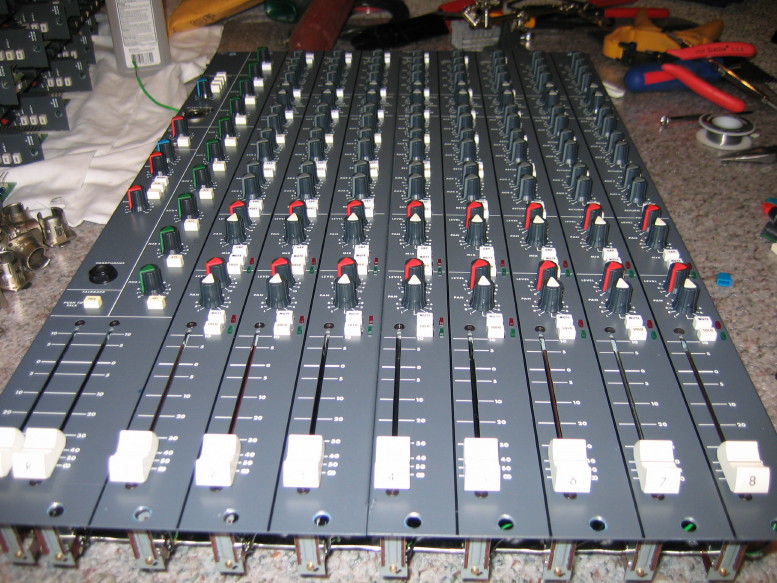
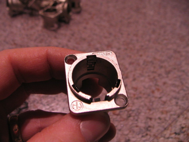
Pin 1 grounding problem: in the case of this mixer (and with most audio devices AFAIK) the best practice is to strap pin 1 of each input or output jack to the device's ground reference (usually the chassis)
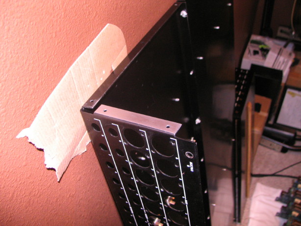
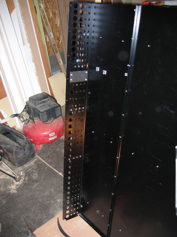
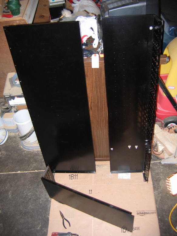
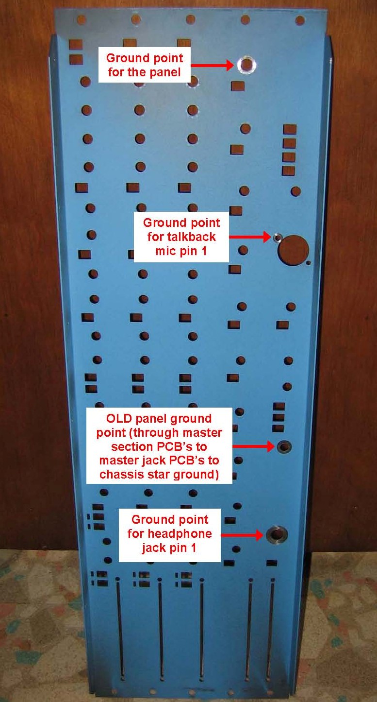
as close as possible to the jack. Substitute "shield" for "pin 1" if we are talking about a TS or TRS jack, but the point is that we are talking about the ground conductor of the audio carrying jack and "pin 1" typically seems to be used in the industry when referencing an audio interconnect relative to this whole grounding thing. The reason for this being a best practice is that the pin 1-to-ground reference connection is a source of inductance; an antenna for garbage interference present in the environment. A steel chassis will not keep all of it out, and while much of it is beyond the human hearing range its artifacts are not...audible noise. So my mixer breaches this best practice by employing a star-ground for every pin 1 connection. That means there is a lug on the backplane next to where the power connector is to which all audio grounds (and so much more) connect. I estimate the total length of wire going between the ground lug and the pin 1 connections on the backplane to be well in excess of 12 yards...
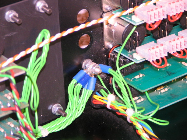
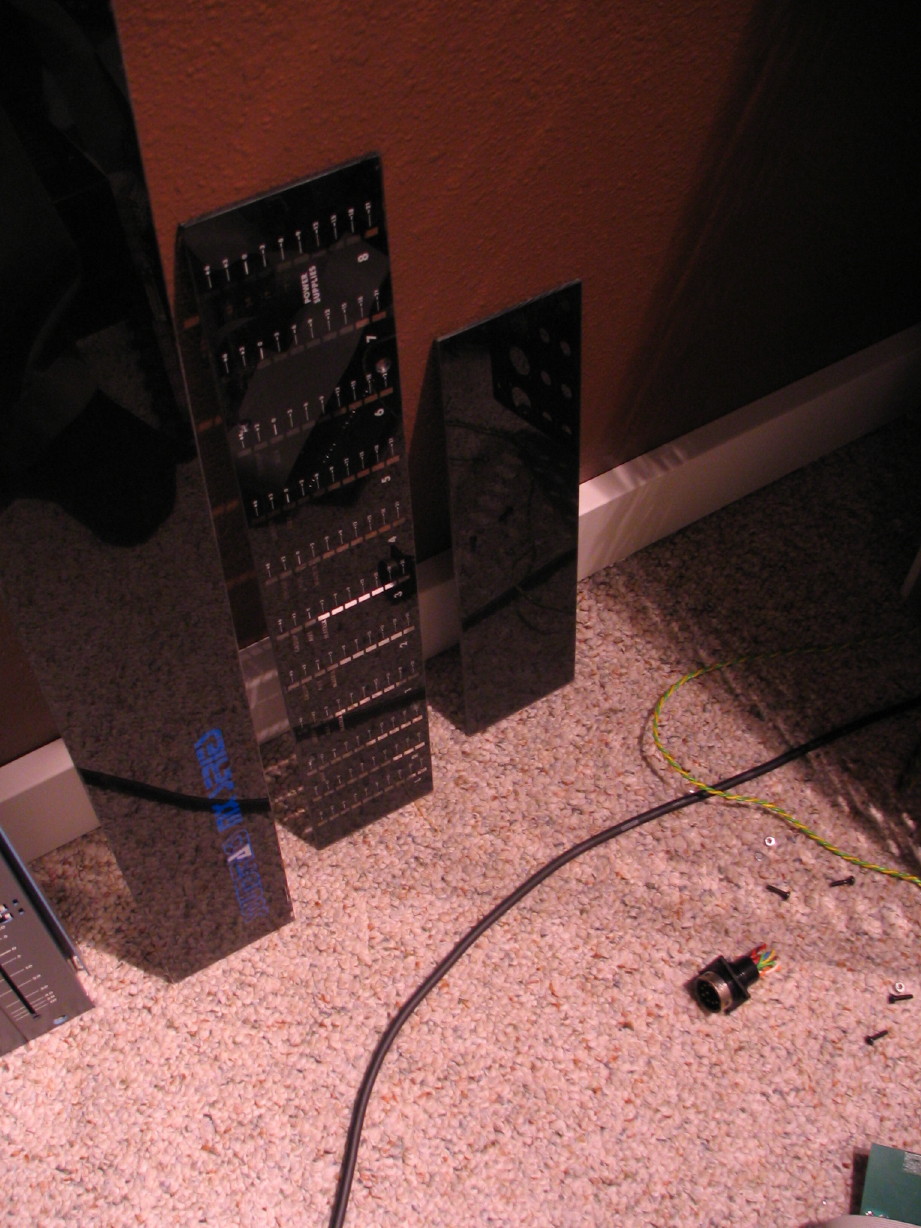
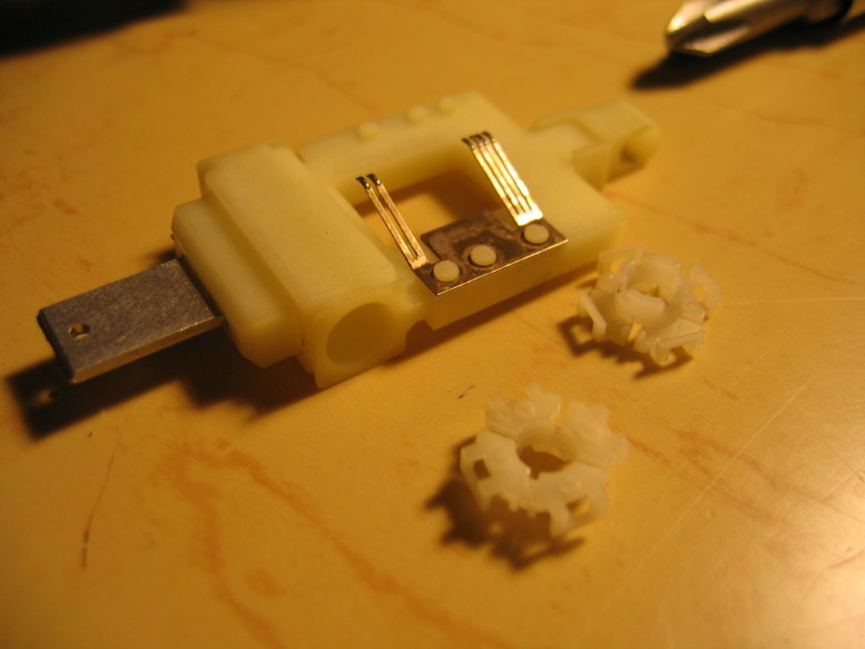
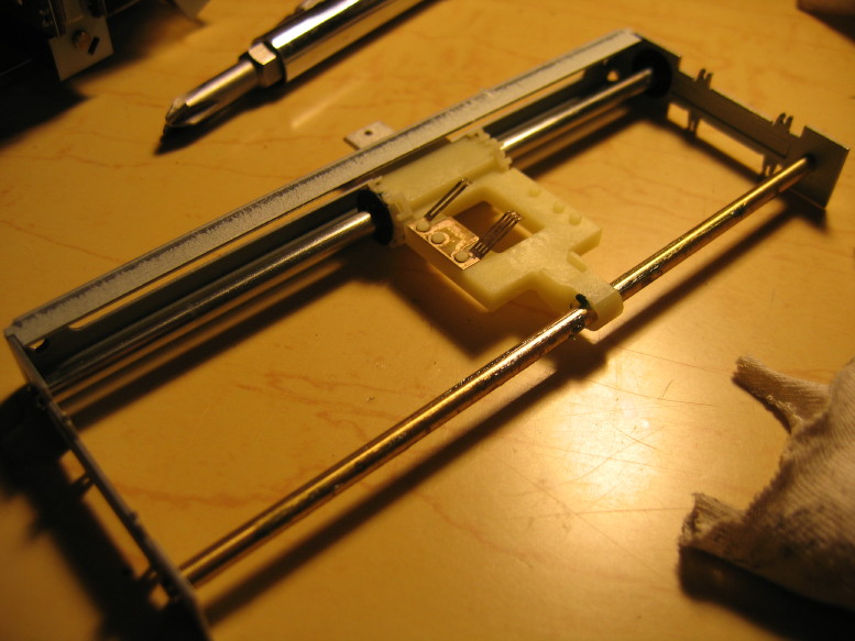
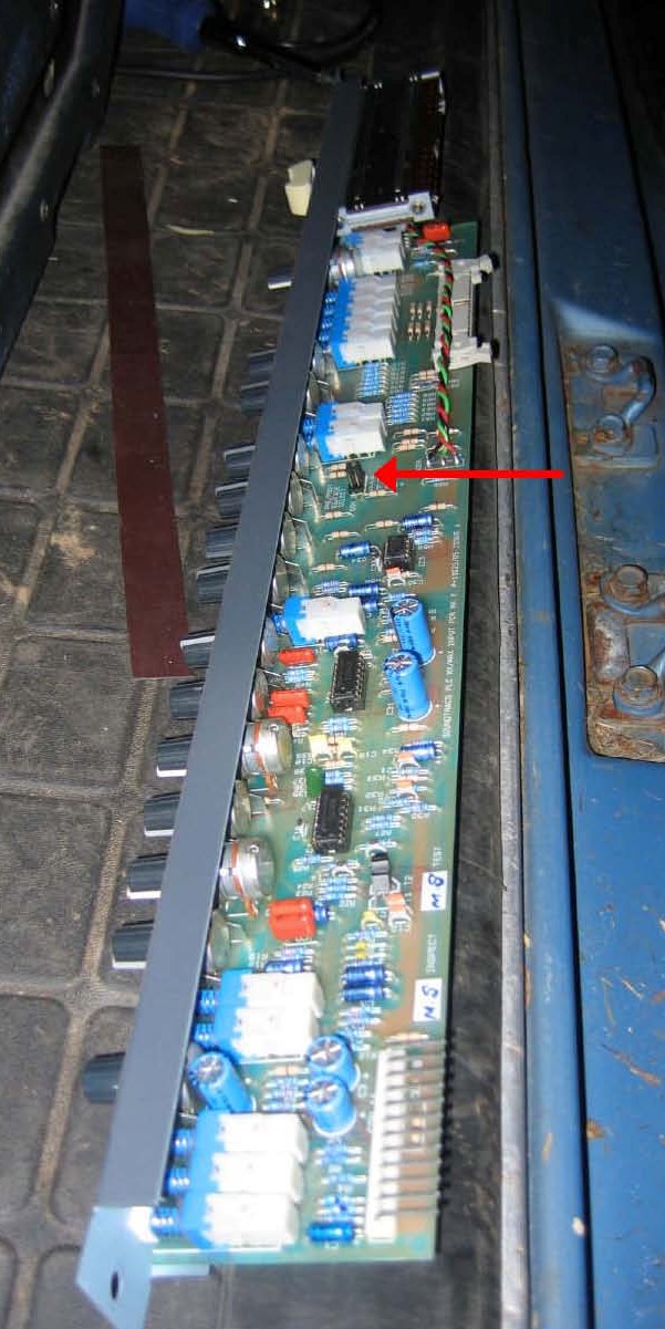
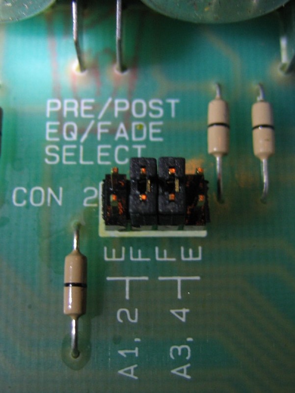
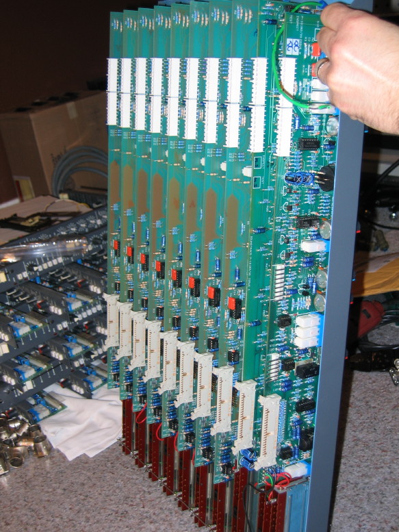
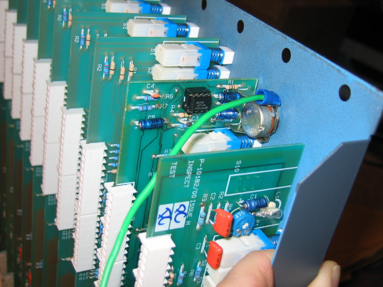
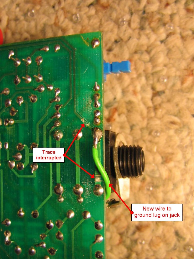
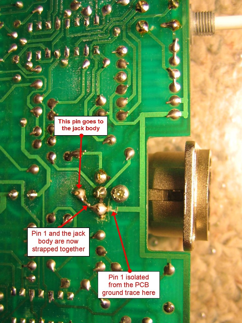
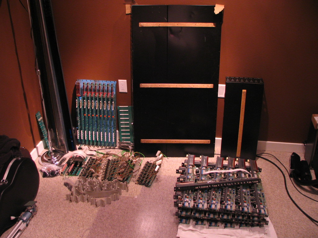
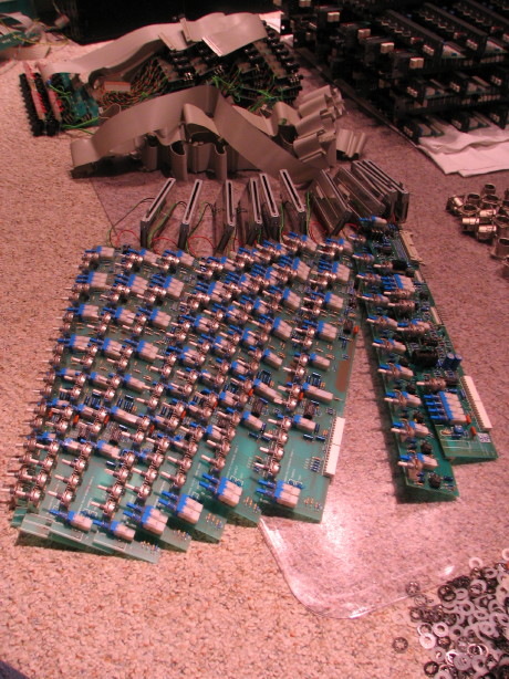
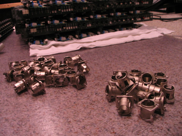
Solution: since all the jacks are PCB-mounted and there are some complexities in how the grounds run on those PCB's, the solution that has been chosen is to bare a spot to the ground trace as close as possible to the middle of each jack PCB, get a wire soldered up to it really well and then drill the backplane and fasten each ground wire for each PCB to its own lug as close as possible to each PCB. Naturally this will involve drilling the backplane for each jack PCB, and there are 20 in all, and baring the paint and using either star washers or keps nuts to ensure a good contact with the chassis. There is the possibility of having the XLR jacks strap directly to the chassis through the connector shell...there are 4 pins from each XLR jack, pins 1, 2 and 3 as well as a ground pin that connects to the shell so in theory I could just link the ground pin and pin 1 together and then make sure that the shell has good contact with the backplane, but because of the way the trace is run on the PCB (it covers about 85% of the PCB) it opens the door for some complications in trying to isolate those, so it is more sensible to just strap each XLR jack PCB to the chassis with as short a length of wire as possible.
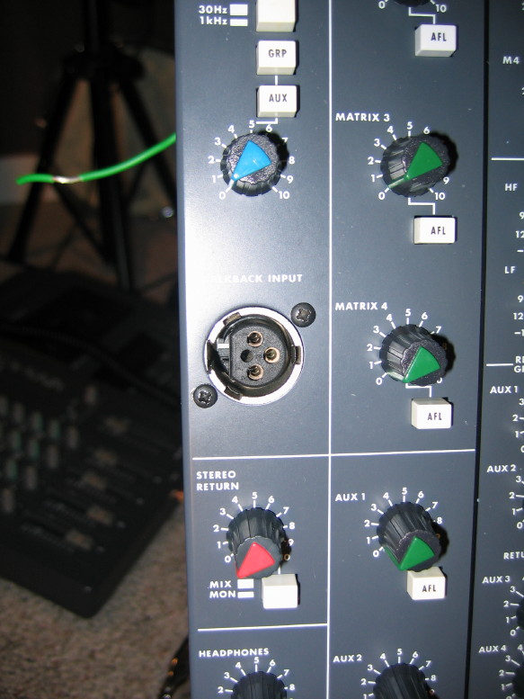
The above solution covers the jacks on the backplane, but there are issues with the talkback mic input jack and the headphone output jack as well which are mounted on the master section chassis dress panel. The talkback mic jack gets its pin 1 reference back at that star ground lug, so I'll need to bond that to the master section dress panel. The headphone jack
actually gets its pin 1 reference back at the power supply chassis. Yep...that's right...through the mixer, through the 10' unshielded power umbilical and round and round all the 0V wiring in the supply and ultimately back to the PSU chassis which is a lame grounding anyway...more on that below. So I'll need to bond that to the master section dress panel as well. In both of these special cases I have additional modification to do to ensure that the
dress panel is properly grounded as well (and this goes for ALL the module dress panels) because as it stands, each panel gets its grounding through an improper path AND there is high potential for ground loops...again, more on that just below.
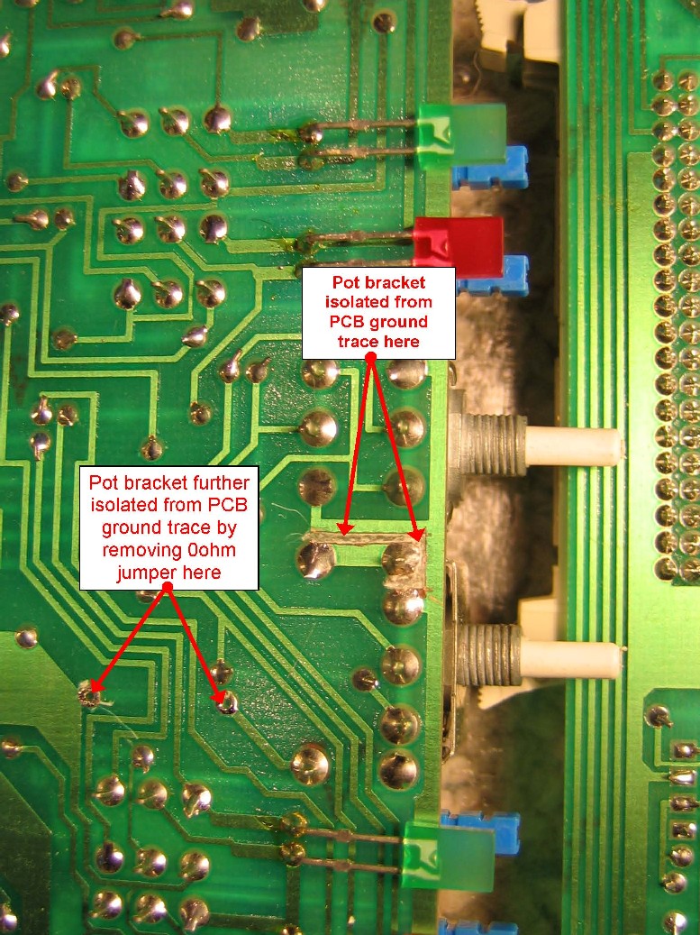
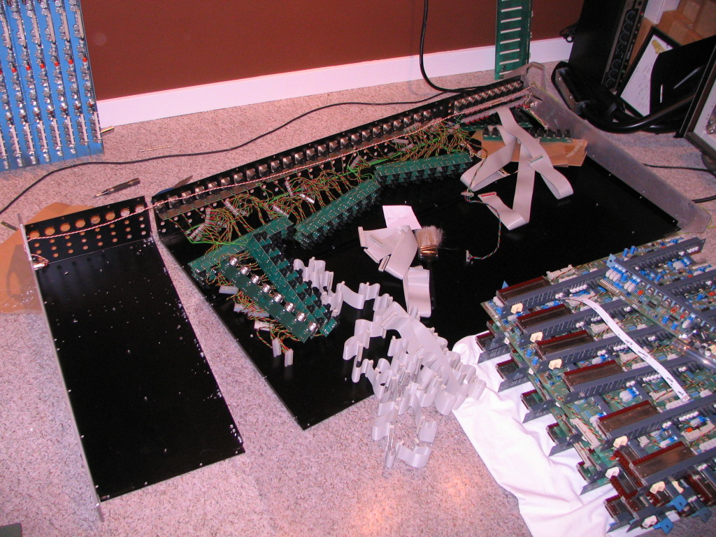
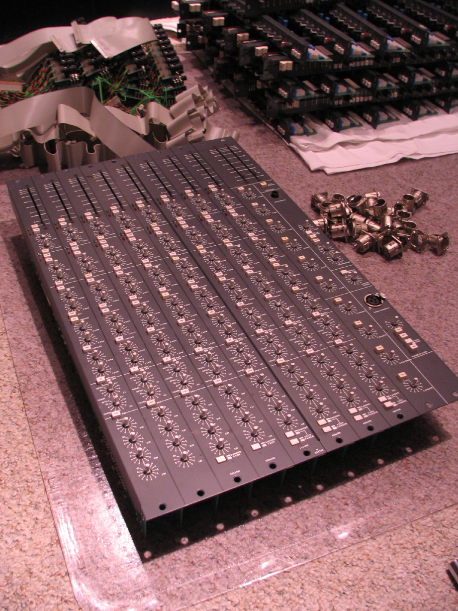
Module chassis dress panel grounding problem: the components of a device's chassis should all have as low an impedance path to the common ground reference point on the chassis. On the Soundtracs MX the input strip panels actually get their grounding through the master section jack PCB's. The ground reference goes from the star-ground lug to the master section jack PCB's through ribbon cable interfaces that connect the jack PCB's to a large connector PCB that goes under the 10 master section PCB's. That's where the master section gets its grounding, and from there the looooong ribbon cable that interconnects all the input PCB's carries that ground to a separate pin of the 40-pin IDC connectors used on that interconnect, and then that pin goes up to the dress panel on each input strip on a dedicated trace through the shell of one of the pots. This is the same way that the master section panels get grounded too. There are all sorts of things wrong with this. Though the panels are all painted, there is the possibility for additional grounding where the panels fasten to the frame which is metal to metal with metal hardware. This opens the potential of ground loops within the system which are an open door to environmental interference noise. The other issue is that it is not the lowest impedance path to the chassis. Channel 1 is at the end of 10' of ribbon cable. Back to the master section for a moment to highlight another wrinkle...that master section dress panel is actually two panels riveted together. Only one of the panels has the path to the chassis star-ground through the shell of one of the pots...the other is supposed to get its grounding through 1 or more of the 7 rivets that fasten the two panels together...there are a couple areas around two of the rivet holes that are bare metal, but the way they put the rivets in the rivets don't really touch the bare metal...Soundtracs was just trusting that there'd be enough contact through paint and hopefully
some contact with those two bared metal spots to provide for grounding. The bared metal spots show some intentional thought into grounding, but the assembly makes the grounding appear as a non-critical afterthought.
Solution: all pots that are presently in contact with their respective chassis dress panel need to be isolated via nylon washers (as all the rest of the pots already are), and EACH dress panel needs to be strapped directly to the chassis. I'm going to accomplish this by baring metal under the TRIM controls and putting ring connectors in between the panel and the nylon washer and then having the wire from the ring connector go to screws I will put in on the underside of the meter bridge housing. There is an extremely good conductive path from the meter bridge housing to the metal left and right panels of the mixer frame and I will be improving the path from those to the backplane. I will put a spade-type disconnect on each wire from each chassis dress panel to the meter bridge housing so that it is still easy to get the strips out. Lastly I'll strap the isolated terminal of the 40-pin IDC connector in with the rest of the grounds. Superfluous I suppose but a quick spot of solder on each channel PCB will keep the ground scheme consistent and not have a dead-end path going down the ribbon cable.
Additional chassis ground continuity problems: as mentioned earlier, each part of the device's chassis should have as low an impedance path to the chassis' ground reference as possible. Right now the main chunk of the bottom panel and backplane (which covers 24 of the 32 channels and the master section) has a slam-dunk grounding as that's where the chassis ground lug is located (right by where the power comes into the mixer...which, by the way, is exactly where it should be). Between every other part of the chassis there exists paint (the 8-channel add-on back plane and bottom panel, the forward bottom panel of the primary section, the end panels for the frame, etc.) There was a
passive approach to continuity here...metal wasn't bared and I think the ideology was that popping the rivets in would be "good enough". I'm not comfortable with that and the best practice validates my discomfort.
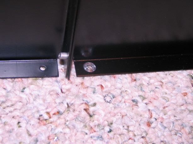
Solution: simple...make sure there is bare metal between all chassis members, and I'm going to go the additional step of applying conductive grease to all bared metal surfaces to improve continuity and stave off oxidation. I've also drilled out and removed the rivets that fasten sections together where I plan on baring the metal and I'll be using machine screws and keps nuts to ensure a tight bond at these locations.
PSU chassis/mixer chassis/0V power rail bonding problems: best practice here is that the PSU chassis and mixer chassis should be directly bonded and to NOT have that bond be co-mingled with DC power rail 0V references until you get to the mixer chassis. The chassis ground interconnect should also provide the shielding in the power interconnect. I've got a little mess here with regard to this. At present the PSU and mixer chassis
are bonded together, but the DC power rail 0V references are tied in the PSU AND in the mixer chassis. Not only that but the connection from the ground prong on the power input socket and the PSU chassis is on, like, a 20 or 22AWG wire to a VERY thin and flimsy lug...so its like
grounded and I want it to be
GROUNDED you know? To make matters worse there is a ground lift switch...I'm sure this was needed but with a proper ground scheme and a properly grounded source of power a ground lift should never be needed...remember that the headphone jack gets its pin 1 reference all the way back at the PSU chassis? Yep...engage the ground lift and now pin 1 of the headphone jack has no ground reference, but it DOES have a 12' antenna on it. As I mentioned, ALL of the DC power rails (+/-17V, +24V and +48V) have their 0V ground reference strapped to the chassis in the PSU AND in the mixer, but at least one of those rails has to go back to the PSU and then back to the mixer chassis to get its reference bond in the mixer chassis. There are two wires in the power interconnect that carry grounds...one is the 0V for the +17V rail, chassis interconnect and one other 0V (not sure which one yet), and the other is (again) the 0V for the +17V rail, and one other 0V (the +24V and +48 power rails share a 0V reference so there are three 0V references altogether). That second one does NOT provide a direct chassis interconnect...its the one that goes to pin 1 of the headphone jack...so everything gets referenced to both chassis ulitmately but it is a mess. And the power interconnect is NOT shielded.
Solution: for starters I'm scrapping the power cable and its connectors. I can't find pins for this thing which has the same plug configuration as a current Hirose connector, but the pins aren't compatible. So, not being able to get the pins out or get new pins it really becomes a mess to try and convert the current cable for best practice operations. 8 conductors are utilized at present on the unshielded cable, and I need 12 minumum over a shielded cable. The cable is fully populated with 12 pins/sockets and conductors, but the chassis connectors on the PSU and the mixer are only populated with 8. I'd need to be able to get the pins out of the chassis connectors at least the ones carrying grounds, and populate the rest of the empty spaces...again, can't get pins, can't get the current ones out, and on top of it all I'd have to get some metal braided sleeving and put over the cable and then find some way to bond that to the chassis at each end. It was easier to get new connector sets and find new cable. I suppose I
could just get two panel-mount versions of those current Hirose connectors but I think that would cost me about $30 and there is no guarantee that the pin layout and pin/socket size on my cable would interface appropriately with the new chassis-mount Hirose units, and I'd STILL have to deal with the shield and chassis interconnect. I found
these connector sets for a good price...they are import and surely aren't going to be the same quality as Cannon or other genuine mil-spec connectors, but I figure they will be better than what's on the mixer, and size-wise they'll drop right in. I found 12 conductor 20AWG cable with braided shield for $1.28/ft. All in all the new cable will run me a little over $40 for the parts including shipping, but with the metal connectors and the braided shield in the cable I'll have a proper and healthy chassis-to-chassis bond, and then I will be using the extra conductors to properly run the 0V references for the DC power rails (two conductors for each taken straight off the outputs of the PCB in the power supply instead of all mixed together with the chassis, and then all bonded to the chassis in the mixer). I'll remove the ground lift switch, or rather convert its function to a disconnect for the 12VAC rail which just powers a couple Littlite sockets, one on each side of the mixer. Also, I'll put in a proper sized lug and wire for the strap from the ground lug on the input power connector on the PSU to the PSU's chassis. The other piece that will be added is a passive noise filter inside the mixer chassis...planning on using 2,200uF low-impedance electrolytic caps with a parallel film cap in between each power rail and its 0V reference before those 0V references strap to the mixer chassis.
At the end of all this I expect to have a mixer that holds up well against the radio station down the street and all the other digital noise in the environment.
I'll be doing the "cell phone test" when its all done: plug all your cables into the mixer for your normal setup but disconnect them from their sources or destinations, strap a 150ohm resistor across pins 2 and 3 of the balanced connections at the ends of the cables, turn all trims up to, say, 2:00, all channel faders to unity, route all channels to the main buss, main buss faders at unity and then turn the output to your monitors all the way down...have a friend initiate a cell phone call about 10' away and slowly turn up the monitor output level...if you can turn it up to your normal level and you don't hear any cell phone interference then have your friend start slowly walking toward the mixer. Keep your hand on the monitor out level so you can cut it quick if you need to. If your friend can walk right up to the mixer with everything setup as listed above then congrats. You've got GOOD grounding.

")
")