famous beagle
Well-known member
Thanks again for the detailed explanations along the way. I really appreciate them.
Your next request is maybe possible depending on what needs to stay connected and what can come loose. I definitely can't get to it as it is now (with the M BUSS PCB still connected and all the cards connected to the front panel).
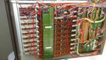
I can unscrew all the nuts on the front panel and pull the cards out, but I don't know how far I'll be able to pull them out with all the connectors still plugged in. (See photo.)
Can any of these connectors be unplugged while taking those measurements?
Your next request is maybe possible depending on what needs to stay connected and what can come loose. I definitely can't get to it as it is now (with the M BUSS PCB still connected and all the cards connected to the front panel).
I can unscrew all the nuts on the front panel and pull the cards out, but I don't know how far I'll be able to pull them out with all the connectors still plugged in. (See photo.)
Can any of these connectors be unplugged while taking those measurements?

") I can see how an alligator clip won't cut it --- especially if it's the middle terminal I'm after. I've searched around for "Flying leads" or "captive clip wire" and haven't found what you showed. Could they be known by another name?
I can see how an alligator clip won't cut it --- especially if it's the middle terminal I'm after. I've searched around for "Flying leads" or "captive clip wire" and haven't found what you showed. Could they be known by another name?