M600 nominal levels

ron-e-g

Member
Hello. been awhile since I've posted but...I've been around. Today I was checking the levels on the board. I engaged the on board oscillator set it to 1K And started sliding the PGM busses to set the VU meters at 0VU (nominal +4). All except buss 3 are close to the 0 mark on the fader scale. But buss 3 has to be raised to +7 VU above the others. I'm now wondering if it's the meter itself or the monitor module. As this board is all balanced (minus the direct outs). How is the best way to connect a tester to the PB-664 patchbay (TT/Bantam) to check the feed of the PGM-outs?

Also, the manual mentions adjusting the semi-fixed resistors on the VU PCB. How would this be done, if found to be necessary?

Ron
 
So I purchased a hand held multimeter. After realizing my leader only had a UHF connector avail. I started looking through "the bay" I got stumped and quickly realized I have no clue what one I needed...so many different models. I decided to get one from the local "Shack". I got the only one that claimed to be a "true" RMS. I engaged the oscillator @ 1kHz I then adj. the PGM fader on PGM 1 so the VU meter reflected 0. I then patched a bantam into PGM out 1. I set the test meter to v and touched the red probe to tip and the black to sleeve. Is that about right? I got a display of 1.9...I was expecting something in the neighborhood of more like 1.23 as this board is +4

What besides everything should I know here? :facepalm:
 
+4 dBu ought to be 1.23v (RMS.) Since the meter is showing 1.9, that means the meter has "0" set at about +8 dBu.

Not knowing the full signal path of this mixer, I can't say where you ought to be making adjustments. However, at the very least, since +8 dBu is coming out, where the meter is saying 0 dBu, you should at least adjust your meter so that it is reflecting the correct dBu output. (Turn the tweaker screw clockwise would be my guess.) Set the PGM out so that the voltmeter says 1.23v, and tweak the meter so that it reads zero. Just my guess. I could be entirely inaccurate here.
 
Thank you Muckelroy for your input. I'm going to have to investigate this further now that I have the multimeter. I'll start by going through the manuals, step by step system check (lengthy). As I understand it..the only adj. that can be made are the VU units and Master Stereo amplifiers.

This all is a big learning curve for this old, ex-carpenter!:eek: I was only hoping to get advise from some others that have already traversed this road.

But, I realize it's a hard thing to do.

Quite a difference, between wood and electricity!! or a hammer and a multimeter!:laughings:
 
What make and model meter did you get? I'm glad it is true rms reading but it may not be accurate even at 1kHz.

Also, if you're not getting a lot of response, keep in mind the M-600 is a fairly rare bird in general and certainly around here...I *think* you might be the only active member in possession of said bird on the AO forum.

Good for us to have you, bad for you to be in such a minority. :eek:

So the group out patch point on the patchbay is for sure balanced? If so, and you are touching the ground probe of the meter to the shield of the TT TRS plug, and the + probe to the tip, you should only be getting 0.615VAC rms, because your meter is (I'm assuming) unbalanced and you're only measuring one leg of the balanced differential signal. What happens if you short the ring to the shield and touch the ground probe to those and the + probe to the tip, what do you measure then?

What measurements do you get when using the same measuring techniques with group channels where the fader is set to unity and the VU meter shows 0VU (i.e. the normal channels)?

Regarding your question of adjusting the "semi-fixed" resistors for the VU meters, boy oh boy I have no idea if they mean jumper adjustments or actually changing out resistors or what. If you have scans of your manual with the schematics, board layouts and parts lists I can probably answer that more difinitively for you, bout outside of that I'm not certain.
 
Thanks sweetbeats for the response. I realize how scarce this model is (trust me) !:mad: This board is indeed all ballanced except the Direct Outs. Too, all the connections are by way of D25 Subs. I think Tascam copied the idea from Neve and SSL. They all terminate into D-Sub (rear)/TT/Bantam Patch bays. Did I mention...headache?
I have the Radio Shack model 2200075 42 Range. I think it's fairly new, as I couldn't find many reviews on it. I plan to look into a fluke maybe the 114 or....any suggestions? I think I would trust a Fluke more. As for the measurements, I have taken readings at all 16 PGM out's with the faders (there are two sets per module) set to nominal and also 0. I get readings like 1.5 & 3.7 and 2.5 ect (touching meters ground to sleeve and red to tip).. Nothing like the 0.615 you mention or the 1.23 the manual mentions.

I do have the M600 Manual, and it includes the part breakdowns.

I don't know if I'm doing something wrong...I don't think so. I have not tried the method you suggest. I will try that next and report back.

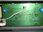
Re; the VU meter adjustments they all have adjustments. see photo.

SANY0331.JPG
 
I have taken some readings of PGM Outs 2,3 &4. No consistency here.
All with faders set to 0
2. 1.9
3. 5.7
4. 4.1

again, I don't get anything close to (1.23). so I don't understand how would I get anything like that? I mean How do I really read 1.9, 5.7 &4.1 readings on the multimeter?
 
Those readings are using your general purpose meter and with the ring shorted to the sleeve, ground probe to sleeve and + probe to tip?

I don't know anything about the balancing circuitry on those group outs, but if the ground is floating and you don't reference it to one of the legs carrying audio you'll get all sorts of results.

AND you need to be using a TRUE RMS METER! :) no point in getting wound up about anything until you are measuring with the proper equipment.

Fluke 114 is good but still not rated for full audio bandwidth. Far sight better than what you have, but still only rated accurate up to 1kHz.

The other wrinkle I'll throw in here is we are ASSUMING the path from the oscillator to the group busses is happy. If it was me I'd be injecting tone of *known* level into each group with an external tone generator (can you do that on the M-600? Are there inserts on the groups?) individually and then checking/calibrating the meters and outputs with that setup...or if te onboard oscillator outputs to a jack on the patchfield patching it into each group one at a time via the patchfield instead of the internal slate patching. Your onboard oscillator and related signal path is likely just peachy, and the first step is to acquire the right equipment and establish the proper measuring conditions.
 
Thanks sweetbeats so in recap. You believe my Radio Shack Model 2200075 True RMS meter is not true? The Fluke 114 is not the best choice for testing my equipment (I hope the Fluke 77) I just purchased is. You mention "the proper" equipment but don't make any suggestions. If you stated what you actually use,That would be helpful to me.

I think I can inject tone at any point I want in the signal path of this board. The "groups" are actually called PGM's on this board and were designed to complement the 16 track recorders. So I believe the 16 buss input and monitor section of the M600 or PGM's should reflect the nominal output (1.23) or+4,stated by the maintenance section of the manual.

If I read 1.5 on the (not true) is that reflecting 1.05, 1.50, 1.005 or can you not answer that given the supplied information?

I believe I have the equipment necessary to test all systems of both this board and my recorders. I'm just in the lurk on how to effectively apply them I guess.

Not being an Electrical engineer Yet!:eek: It's all a little daunting and overwhelming but do-able for me if I can learn a piece at a time. Like..how do I read 1.9,5.7, or 4.1 on this (not true) multimeter. If that makes any sense.
 
Back
Top