Capacitor Polarity on Tascam 80's era PCB boards (388, 308, 38 etc)

LUNE

...a pieds joints
on one of my PCBs i find a capacitor that is not sitting with its polarity the same as the others (edit: i.e., it's in backwards, the actual capacitor is in reverse to what the board has printed). I immediately assumed this must be some kind of capacitor where polarity doesn't matter, but now i wonder. In studying the PCB boards/parts list in my 388 manual I'm coming across 3 different styles of capacitor symbols. can anyone explain to me the exact differences here?
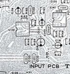
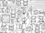
input pcb closeup capacitors copy.jpgEXHIBIT A: these would be the obvious capacitors with polarity symbols (such as c126- sorry for the bad picture)), it has the dark circle on the negative side and shows a "+" on the positive side.
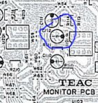
monitor pcb closeup capacitors w circle.jpgEXHIBIT B: this is the actual capacitor that appears to be in 'backward' (circled blue, C112) , the positive side is in the black dot section. anyway, in this symbol there is no "+" but it appears to be polarized none the less with the black dot on one side. is the polarity on this capacitor important? and what if the capacitor that is in the actual board is in reverse polarity from the symbol on the PCB diagram and the symbol on the actual PCB board? (I got this machine from the original owner and I'm sure he never had it recapped)
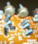
R.P.-pcb-close-up-capacitor.jpgEXHIBIT C: here we have electrolytic capacitors that appear to be polarity inconsequent (such as C115).

so can anyone shed a little light on the polarity of EXHIBIT B and why one might have ended up in reverse of all the others? and for curiosity sake, what is the difference between the symbols with the "+" and the ones without.

I am going to be recapping this and it makes me wonder which way i should recap it: the way it was, or the way it "should be" according to the PCB's.
this (monitor) PCB is my best guess to where my "muffled oil in frying pan" sound is coming from. (see: [URL="https://homerecording.com /bbs/showthread.php?p=3311431"]https://homerecording.com/bbs/showthread.php?p=3311431[/URL] )

thanks for any thoughts on the matter.
 
Last edited:
I don't get it.

You must have no real-life worries to be hunting down capacitor polarities! :)

Seriously, I can't imagine that there's a problem here. Some types of caps have no polarity, like ceramic, while others do, like electrolytic and tantalum. The reason has nothing to do with the circuit, but with the capacitor material technology and chemistry: DC voltages applied the wrong way will ruin them, sometimes quite dramatically.

The "b" image is a component placement drawing, and the polarity orientation of the caps follows the DC bias in the circuit it's connected to. The direction is an artifact of the PCB layout.
 
: DC voltages applied the wrong way will ruin them, sometimes quite dramatically.
exactly why I'd like to be sure of whats going on here, if the polarity on Exhibit B is important and the capacitor in place is running opposite polarity to what the PCB / Component Placement Drawing is suggesting, well, it's an obvious problem.

The direction is an artifact of the PCB layout.
:confused:I guess you thought I was talking about the physical placement of the capacitor design? (as in this one has its positive polarity to the right, this one to the left, this one up or down on the PCB?):confused:
anyway, thanks for taking the time to respond even if you didn't understand the question i was trying to pose. I may not have a succinct jargon when talking about these things and with a longwinded post perhaps its easy to misconstrue. i'll try to reword the original posting to make it more clear.

however, being new to the re-capping realm I would still sure like to know whether my C112 capacitor was somehow misassembled or if the polarity doesn't matter in this case. Yes, it would seem EXTREMELY odd for one of these capacitors to be assembled backwards, and I would have assumed it would malfunction drastically if it was polarity sensitive, but these symbols look to me like polarity sensitive capacitor symbols. if anyone can corroborate this or tell me how in this case polarity doesn't matter I'd greatly appreciate it. I wish I could post a close up picture so you'd all know that the capacitor C112 REALLY has its negative polarity attached to the positive pole on the PCB board, but my camera is not up to the task.

here is a sad attempt, if you have the manual you could see that the light strip side (negative) is on {what I understand to be} the positive side. (or you could just believe me). Its the only one I can find like this from all the boards I have out.
capacitor polarity 2.jpg

You must have no real-life worries to be hunting down capacitor polarities! :)
Yes, life is pretty good when one's concern of the moment is getting one's relic recording machine recapped properly...:)
...unfortunately, rent's also due in a couple days.:(
 

Attachments

  • capacitor polarity.jpg
    capacitor polarity.jpg
    28.3 KB · Views: 256
O.k., ...

I get it. Well, it could either be that the
  • cap is installed backwards;
  • or the silkscreen is wrong;
  • or for that cap technology, polarity doesn't matter;
  • or, in that part of the circuit, there's no DC across the cap.

Can you measure the DC Voltage across the cap while the machine is powered up?

Perhaps best to ask another owner to examine theirs.
 
Go with the schematic -

I tend to rely on the schematic which shows the positive lead of C112 going to pin 7 of U101.

I have found errors in schematics. Did you pull the cap?

This appears to be an error in the silk screen.

un polarized caps are (eh) un polarized and can usually be placed in either way. Ceramic disc caps are un polarized as well as bi-polar electrolytics.

Polarized caps (most electrolytics) do need to be put in a specific way.

This cap (C112) is an electrolytic coupling cap which "on average" has 0 voltage across it. It does get reversed biased for half of the time no matter which way you put it in. In reality it would be better to replace it with a bipolar electrolytic of the same ratings. But that may be overkill on this board.

On electrolytic caps the negative side is typically marked and the positive side has a longer lead (out of the box). The positive may have a +. The mark indicates the outer foil and the + or lead length indicate the polarity.

THink abouut the construction of an electrolytic cap and many others. It is 2 layers of foil with an insulator between them (Yes I know this is an abstraction) that have been wound into a roll. The result is that there is an inner foil and an outer foil. The marking on the cap is typically the outer foil. This usually means that the inner foil is the positive and the outer the negative (which is often grounded). The outer foil is more subject to picking up RFI than the (shielded as it were) foil. SO you would put the inner foil to the input of the next stage where is will not feed RFI to that stage and the output from the prior stage driving the outer foil.

Regards, ethan
 
thanks Ethan, for the clear ideas, and the suggestion to follow the schematic (and the extra info on the inner workings of capacitors!).

It does appear to be the case that the silk screen is an 'anomaly', but its only partially incorrect, I now see. I've been looking at the black circle (white on the actual pcb) because it was more obvious to my eyes than the bowed or straight bit of the symbol just under the actual capacitor (which is the 'real' marking of polarity I guess), so I suppose its just an anomaly, but not exactly printed wrong either. so I'll replace with the same polarity as it is (the old ones are still in the board) and as shown in schematics (and actually what the silk screen shows on the PCB board, but hopefully people here can understand how I was fooled by the misplaced 'black dot' on the board and the diagram:o).

I've scanned the manual to show this anomalous C112 symbol with pictures here: case closed. :cool:
mon pcb c112 schematic.jpgmon pcb c112 diagram.jpg

so Ethan, out of curiosity, what is the difference in the capacitor symbols when they clearly demarcate a "+" sign on the outside or merely show polarity with the 'bowed' or 'straight' line? that is to say, what is the difference between the symbols represented in EXHIBIT A and EXHIBIT B?
they both are electrolytic capacitors that require the proper polarity placement, but why the added "+" on some symbols and not others?
 
PCB layout and silk screen artwork are (were) done by hand by artists not engineers. There are ample examples where the schematic and artwork do not match. It can be easy for such errors to creep in during that period. Now of course most of the PCB layout is done by auto router software with much less chance of this type of error.

As for caps and other parts symbols. They are just part of a symbol library and during the creation of the PCB layout the artwork designer selects the symbol based on the BOM (bill of materials). Today of course the computer knows what symbol goes with which part.

Straight lines mean a non-polarized cap. Straight on one side and curved on the other is an electrolytic. But things are not cast in stone and there are many variations in symbols. You roll with the punches especially with 30+ year old hardware.

I did once did a recap of an Ampex ATR-700. I just plugged the caps in based on the silkscreen. On power up there was a loud bang. Of course the silk screed and schematic were at odds. Replace the cap and away we go.

Your board is not blowing up....

Regards, Ethan
 
Straight lines mean a non-polarized cap. Straight on one side and curved on the other is an electrolytic.
Regards, Ethan
With all due respect, that is simply not so. The symbol for a capacitor has always been one curved, one straight line; polarized caps add the "+" sign to the symbol.

I've done a lot of circuit design that was captured on everything from paper to high-end cad systems. Typically, the silkscreen artwork is something the design engineer has nothing to do with; it's developed and maintained by the cad department, and is taken as a part of a part model from a library by the PCB designer, someone the design engineer rarely would know or meet (in my experience).


Of offense taken. And it is not so simple... How far back does your always go? Do you remember "A Boy and a Battery"? Have you made a Leyden Jar? The point I'm trying to make here is that before CAD tools for electronic design came along there were no software enforced standards and that the artwork designer worked alongside the production design engineer to get the product out the door.

Oh just to add to it take a look here: http://en.wikipedia.org/wiki/Electrolytic_capacitor

One more set of symbols: http://library.thinkquest.org/10784/circuit_symbols.html

And while I'm thinking about it not all countries use the same symbols as the US.
Regards, Ethan

PS I should have said in general and in the 1980's
 
You make my point.

You can't rely on a curved line to indicate polarity, since - it isn't always used to indicate polarity. A "+" sign is a sure thing.

There are standards for symbols: that's what's nice about standards, there are so many to choose from! :)
 
Well then I amend my statement to include:

But don't use a curved cap symbol to indicate for sure that it is electrolytic.

In this manual (the 388 copyright 1985) electrolytics are shown with the curved cap symbol with or without the + sign (but almost always with a value and voltage) and bypass caps and most if not all non-polarized caps are shown with a set of straight lines.


I suppose you will need to amend your statement:

"The symbol for a capacitor has always been one curved, one straight line; polarized caps add the "+" sign to the symbol."

Let's not confuse anyone working on older equipment with absolutes.

Regards, Ethan

PS You Sail?
 
Back
Top