Another Akai MG1212.......

I may be jumping to conclusions here, and it could me more intermitent shenanigans. I went ahead and opened up the relays on the bad cards. Sweetbeats mentioned this earlier. They opened up fairly easy and I cut a thin strip of paper soaked in a little deoxit and ran it through the contacts.
After doing this, things seem to be working now. Even when I nudge the card when playing back, Im not getting the muffled rumbnling sound and the playback is not fading in and out.

Hoping this is it. I'm gonna keep doing some more recording tests on the 2 suspect tracks throughout the day to see if the fix holds.

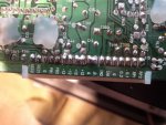
Edit... Sorry about posting the pic.Couldn't delete it. I was gonna ask about the two +12 solder points that are bridged together on this one card. I just realised they they share the same path. It's not like that on any of the other cards.
 

Attachments

  • IMG_20161223_103334.jpg
    IMG_20161223_103334.jpg
    1.8 MB · Views: 23
Ive just caught up with this thread and am so impressed with all your efforts. Well done.
I also have a slamming door issue and now I think I will try your fix for it.

In regard to the Program cog, I think if you have anymore issues you could drill some very small holes and insert some small diameter wires in different areas and then epoxy around this. much like reo bar for concrete construction as you are creating a structure that will strengthen the overall repair.
Oh by the way, I had a problem with a few buttons that were intermittent, a few channel select buttons, so I took them out and replaced with some from my salvage Akai MG1212.
 
Thanks! The repair to the cam is holding with the epoxy putty and everything is running smoothly.
I replaced the eject button with one I pulled out of an old unused cd player I had kicking around. That now works. But, I think I messed something up while doing that. To get to the bottom of the transport board you have to unscrew it from a frame that it's attached to. While testing the eject button I think I fried something as I didn't screw the transport board back down to the frame while testing ans some of the solder contacts on the bottom must have been resting on the frame. It blew a fuse and the big track display would not light up. I replaced the fuse and now only part of the display works. All the rec lights light up and flash when selected, but some of the other function lights won't light up on the display. Even though the functions work. The record button led no longer lights up too. But the rec function works. Kind of annoying as all those things used to fire up and now they don't because of my carelessness. The control button that stripes the track for the counter to work is also not tripping the control relay. The relay clicks when powering the unit on, but the button isn't doing it's job. So I don't really have any counter to work with.
Other than that, I have been doing some recording tests and it sounds great. Hopefully will post a tune soon.
 
I just wanted to say again how impressed I am at the work you've done. You've gone where few seem to have gone and bucked some of the transport reliability reputation of these machines. It's really cool.

What fuse blew?
 
I just wanted to say again how impressed I am at the work you've done. You've gone where few seem to have gone and bucked some of the transport reliability reputation of these machines. It's really cool.

What fuse blew?

Thanks Cory.
I blew one of the 500mA fuses. Upon looking at the underside of the transport control pcb, I noticed a few white powdery looking marks around some of the solder points. I'm guessing these were the spots that maybe went "poof".
Im not the best at tracking electrical faults down. It seems everything is functioning though, but it would still be nice to have the display, and record button LED working again.
 
So the 400mA fuses F1 and F7 protect two low-voltage AC rails (like around 4V). I think...and I'm not certain, but I *think* that AC power is dedicated to illuminating the LCD and status LEDs...that's why its dark...I *think*. Man I wish I had mine apart and I could give you a lot more specific direction.

Can you find connector P28 on the system control board? It should be a 9-pin connector. If possible, with the machine powered, see if you can measure for AC volts between pins 1 & 2 of P28. I think you should have about 8V AC there between those two. If you do, and I don't really have a clear idea from the service manual PCB layouts how this is all put together, but it looks like there's an assembly mounted to the system control board with alllll the Buss A, Buss B, track and record status LEDs, right? And there is a boat-load of connections going in and out of that. Again, I don't know what you can actually get to or see, but if you can see the terminal numbers on the LED assembly, there should be a grouping of three terminals at one end numbered 150, 151 & 152, and another grouping of three terminals at the other end 77, 78 & 79. Again, with the unit powered and your meter set to AC volts, put one probe on any of the 150/151/152 terminals, and the other on any of the 77/78/79 terminals. You should have about 8V AC there too.

If any of that doesn't make sense, or isn't feasible, can you put up a pic so I can see what you are looking at or can get to?

If you can accomplish the above, report back your findings.

Maybe the picture would help regardless.

Also, to address a question you had about the bridged solder points on the R/P card in post #61...I think you've figured that out already, but, yeah, sometimes they'll use two terminals of a multi-terminal connector for power just to increase the current potential...one of your cards clearly shows the person assembling that one card had had coffee and was a little excited with the solder and blobbed more on. Absolutely no concerns with that.
 
Thanks Again! I don't have it opened up right now, but will most likely do that tommorow or sometime over the weekend.
Here is an older picture that I posted earlier of the control board. It's not a good close up. I will post another pic later.
The big screen is the assembly that you are talking about right?.Yes, lots of connections on that. As you can see the row of functions that are lit up at the bottom of the screen. Those still light up. They indicate playback. The 2 that are over to the left, those are the Buss A and Buss B indicator lights, they no longer light up.

The channel indicator lights for bus A light up, but the track lights don't. None of the bus B indicators light up at all.

But it doesn't affect the function. I'll have a poke around with the meter. May need a little guidance on that though.

IMG_20161209_144823.jpg
 
Can you find connector P28 on the system control board? It should be a 9-pin connector. If possible, with the machine powered, see if you can measure for AC volts between pins 1 & 2 of P28. I think you should have about 8V AC there between those two. If you do, and I don't really have a clear idea from the service manual PCB layouts how this is all put together, but it looks like there's an assembly mounted to the system control board with alllll the Buss A, Buss B, track and record status LEDs, right? And there is a boat-load of connections going in and out of that. Again, I don't know what you can actually get to or see, but if you can see the terminal numbers on the LED assembly, there should be a grouping of three terminals at one end numbered 150, 151 & 152, and another grouping of three terminals at the other end 77, 78 & 79. Again, with the unit powered and your meter set to AC volts, put one probe on any of the 150/151/152 terminals, and the other on any of the 77/78/79 terminals. You should have about 8V AC there too.

If any of that doesn't make sense, or isn't feasible, can you put up a pic so I can see what you are looking at or can get to?

If you can accomplish the above, report back your findings.

Maybe the picture would help regardless.

Ok. I followed your instructions. Getting a reading of around 8.61 between pins 1&2 on p128 and 8.53 between terminal 77&152 at either end of the LCD.

Here is a pic of the p128 and the terminals of the LCD...

IMG_20170106_155127.jpg
 
The white spots are located under the rows of pins under the LCD display. Not sure if this indicates that anything got damaged. But it does look suspect.

Here are some pics...

IMG_20170108_104037.jpg

IMG_20170108_104159.jpg
 
When the board is mounted, what is directly under those spots? Is it possible to post a picture of that?
 
I found a few more small white spots starting from the bottom right corner of the LCD
So....from the right side bottom of the LCD counting back here are the locations....

IMG_20170108_121647.jpg


And from the top side right counting back about 30 pins....

IMG_20170108_121728.jpg
 
Can you check the tracks that have the suspect white marks for current potential(I don't know the right term). Say if you find a solder point on the suspect circuit board track before the suspect damage point and find a solder point after and use your multi meter to prove the current flows through this suspect point. I guess a process of elimination. If you can say without doubt that any track that has a white powdery marks has no compromised current flow through then you could move on.
 
Just checking, you're aware the 'LCD' is actually a VFD, right?

Oh yes. That's a good point. Anything in particular about that type of display that might be useful considering his symptoms?

j.harv I'm at a bit of a loss still. It seems the power that pertains to the fuse that blew is getting to the VFD, and there are no components in between. You could check for continuity from fuse F1 to the set of VFD terminals 77/78/79, or fuse F7 and terminals 150/151/152 (this is what deslog is suggesting). It wouldn't hurt. But the *poof* marks on the trace side of the board look like they possibly came from another assembly...like something blew on another board. That's why I'm asking what is mounted just underneath that System Control board.
 
There is nothing but a zinc annealed metal removable chassis under there. This supports the System control board. Under that is the power supply board. I cant see how it could of happened there.


System Control board out of the way (FILEminimizer).jpg


System control board out of the way 2 (FILEminimizer).jpg

Try and protect the circuit boards from touching other things( I no you learn't your lesson). In the photos I placed a peice of wood across the top of the chassis to help support the Mechablock(recording section) and put a piece of foam under the system control board to protect it while I was working on other things. These are old pictures of mine.

The thing is we don't really know if YOU actually caused the new problem or it was a coincidence and just another problem due to moving the circuit boards around. Just think about it, the recorder mixer you are working on is about 32 years old. Any wires that you see that have that brown adhesive/sealer stuff around, check to see if there is corrosion as this goop seriously decomposed over time and encourages oxidization and rust. I had to repair a few wires like this.

Transistors (FILEminimizer).jpg

Also check the black strap wires going to the board and display. I broke a few by moving the board around. especially were they put the GOOP.
 
Last edited:
I'm no expert on VFDs and the pinout for this one is going to be hard to find unless it's in the service manual as it's almost certainly a custom part.
However, it will require several supplies, e.g. for the heaters and the anode (and I think the anode wants more like 12-15v, 8v sounds too low). What I am wondering is if the VFD has multiple power inputs for different parts of it, since it's quite big, and that some of those might have gone down. But that's just guessing.

I can't remember if this has been suggested in the thread but since the event seems to have taken out a bunch of LEDs and part of the VFD, it might be worth turning to the LEDs. For example, do the dead LEDs actually work? My Fluke will light up an LED if you use the continuity tester so it would be interesting to inject power into one of the LEDs and see if the LED itself has blown or whether the problem lies in the switching logic.

EDIT: but be careful. Modern LEDs seem to be happy accepting AC, in that they don't die if given the wrong polarity. However LEDs of this vintage might not.
 
Thanks guys.
I can live with it because it isn't affecting the functions at all, well, except for the control track button not tripping the control relay.That's the one thing I would like to get going because it's what make the counter work.
It's just one of the OCD things, like having a vu meter bulb that's out. You just want it ito work.

I'll have a few more attemps at sniffing around and checking wires and such. If nothing, then I'll button it back up and start doing some recording and revisit the problems in the future. I'm thinking maybe there is something in the VFD that can be damaged to the point of it not being repairable.
I'll keep looking...

It's possible. Apparently the heaters are usually made of very thin wire and can blow if given too much voltage.
 
Back
Top