How to test

Does the amp motor boat with the input pot at zero?
If not are you feeding the guitar into the "LF rolloff" input via the cap? If not try that.

Also if the amp is stable with no input it is because it was never meant to be fed from the odd, shitty impedance that is an electric guitar! Do you have a pedal? Try that since it will present a nice low impedance to the first valve's grid.

If it MBs with the grid at earth lift the feedback resistor and cap, 3k3 and .001.
If it is still not stable I am a bit stumped but a voltage table might throw up an idea or two! OTTOMH I would say the coupling caps, C26/27 were 5 times bigger than they need be (and 20x bigger for guitar work!)

V4 is not a "pre amp" valve. It is the voltage driver to the output valves. V5 is just a PI of a type known as the "Paraphase" aka "Concertina" inverter and has a gain of one!

Do you intend to use this AS a guitar amplifier or for Hi-Fi?

Dave.
 
I have been cutting and painting siding for the house all day and have not been able to get back to it. I am really using it for learning purposes, but it looks like it might make a good guitar amp? I know harmonica players love these things and pay good money for them. All the ones I see on ebay go usually for over 200.00 and I bet they are all bought up by harmonica players. I was feeding the guitar into the joe meeks preamplifier then feeding the amp. I will try all the things you mention as soon as I get time and will report back. I am an amateur and there could easily be a wrong connection or drop of solder somewhere that might screw up everything but I have been very careful to pull only one component at a time and replace it so I don't make a mistake, etc.
 
I am not allowed to disclose those details at this time until I consult with my esteemed colleague, without the risk of appearing to know anything.
 
"If it MBs with the grid at earth lift the feedback resistor and cap, 3k3 and .001."
I did not follow this advice right away, for one I wasn't sure which grid we were speaking of, then I forgot to do it, and when I did, voila, there she was. I am awaiting an explanation that will probably be over my head and I will have to profess my ignorance once again, but hey, I did finally get her fixed after two years of unsteady work.

---------- Update ----------

and, I didn't kill myself.

He is too modest. He was inspired. He disconnected the series CR network that feeds Negative Feedback to the PI valve.

Now, NFB must be in such a phase mode that it reduces gain at ALL frequencies. This is hard in a valve amplifier since we have all sorts of phase modifying reactances. Coupling and decoupling capacitors, stray circuit and valve capacitance and, the devil in this case, the less than "perfect" OPT. Clearly the replacement traff was slightly different in ratio, interwinding capacitance, inductance and leakage inductance from the original. Thus, all bets were off phase wise and the amp took off.

It is quite possible that a bigger resistor value, 3k9, 4k7....will allow feedback and keep stability however, NFB is of dubious value in a guitar amp, many, most, do without including the legendary AC30!

Dragonworks...Eee me, MUCH easier than the wee boxes!

Dave.
 
I have erred!

The feedback does NOT go to the PI as with most gitamps but follows the hi fi practice of going to the cathode of the input valve V 4. This makes instability even more likely.

Then the 3k3 and cap are in PARALLEL not series as I said. This shows the folly of trusting to a circuit memory, especially when you are as old and medridden as I AND have only just started coffee #3.

Now that I HAVE the circuit under my nose I see that the shared cathode bias resistor for the 6L6s is only 200R? With an effective anode voltage of 359 that puts the anode dissipation at around 20W per valve or 75% of absolute max of 30W. The "book" value for a shared Rk is 220 or 270R and that for lower HT voltages.

'Twere I, I would replace the resistor with a 330R 5, better 10W component and if the sound was worse, tack in resistors in parallel until it improved. I bet you will get a good sound at a dissipation of around 15W per valve quite easily.
Why do this? Heat is always a killer, especially of electrolytic capacitors and anyway valves is expensive! Why run the bllx off them needlessly?

Once this project is d and d'ed you might like to investigate a mod to "fixed" bias for the OPValves? Probably more power, certainly a different "sound".

Dave.
 
I was going to correct you but then I thought who am I?
anyways, should I throw the original OPT in there and see whats up?
I will go with your advice and replace the resistors, I probably have some kicking around.
 
I was going to correct you but then I thought who am I?
anyways, should I throw the original OPT in there and see whats up?
I will go with your advice and replace the resistors, I probably have some kicking around.

You don't have refit the old traff perfectly. Just diss' the primaries from the anodes and tack in the old unit and hook a speaker to the appropriate winding. Sit the traff on a handy bit of ply across the chassis. I have done this countless times to checkout variant transformers for specification, never a problem.

If it works (thrash 'bugger!) you have a spare OR you can build another amp!

Dave.
 
the old opt is quite physically bigger and gray, the amp kinda looks funny to me with the "small" black OPT in there, so if the original is good I am going to put it back in and keep the Stancore Tranny as spare parts or for a build somewhere in the future.
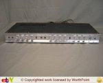
I have an old Teisco stereo tube preamp that I cannot find a schematic to that I would love to fix and put in front of this amp. I think it is the last one in existence and if I don't fix it, it will go extinct, but without a schematic I think it will take someone with more knowledge than myself to tackle it. I have carried this preamp all over the country with me for the last forty years.

NOW! You tells me! I was under the impression that the new traff was a close to exact replacement. THIS is why the feedback is screwed!

Re the pre amp. I will have a search too and ask some peeps. Take some photos of inside and out. Valve circuits are all much of a muchness and pretty simple to fix. One thing, if you want to use a magnetic phono cartridge with a turntable, very few valve designs had low enough noise or enough gain for "modern" cartridges, e.g. Shure V15. This is easily fixed however with an aperiodic booster in the line using a low noise op amp (just don't tell the audiophool cognoscenti!) .

Dave.
 
NOW! You tells me! I was under the impression that the new traff was a close to exact replacement. THIS is why the feedback is screwed!

This would suggest that the old traff was the source of the problem and the new one is slightly out of spec, right?
 
This would suggest that the old traff was the source of the problem and the new one is slightly out of spec, right?

If the old traff has passed the "heater volts" test then it is probably ok. Worth a punt, worse case blow an HT fuse.

Dave.
 
NOW! You tells me! I was under the impression that the new traff was a close to exact replacement. THIS is why the feedback is screwed!

Re the pre amp. I will have a search too and ask some peeps. Take some photos of inside and out. Valve circuits are all much of a muchness and pretty simple to fix. One thing, if you want to use a magnetic phono cartridge with a turntable, very few valve designs had low enough noise or enough gain for "modern" cartridges, e.g. Shure V15. This is easily fixed however with an aperiodic booster in the line using a low noise op amp (just don't tell the audiophool cognoscenti!) .

Dave.

According to the sams photofact and mascos parts list it is a direct replacement? Stancor A-3307. It stated I would have to drill new holes, which I did. They had no directs masco part listed and there is no markings at all on the original. They had the Stancor, a Merrit A-3101, a Chicago PCO-80 and a Triad S-35A, all listed as direct replacements. The Stancor was the first one I came across.
 
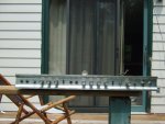
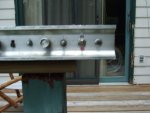
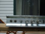
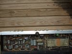
Here are the existing pictures I have of the Teisco,
 

Attachments

  • DSCF0028.JPG
    DSCF0028.JPG
    591.5 KB · Views: 14
  • DSCF0029.JPG
    DSCF0029.JPG
    563.6 KB · Views: 14
  • DSCF0030.JPG
    DSCF0030.JPG
    578.5 KB · Views: 14
  • DSCF0031.JPG
    DSCF0031.JPG
    632.9 KB · Views: 14
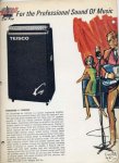
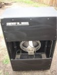
It came from a Teisco King amplifier. The amp was in the cabinet and the preamp sat on top.
 

Attachments

  • teisco king.jpg
    teisco king.jpg
    50.9 KB · Views: 14
  • teisco.jpg
    teisco.jpg
    46 KB · Views: 14
  • cab.jpg
    cab.jpg
    22.1 KB · Views: 14
  • cabamp.jpg
    cabamp.jpg
    37.9 KB · Views: 14
I have gone through it some, when I first got it nothing happened. As I read Jack Darrs guitar book I realized it was a half wave voltage doubler circuit as a power supply and upon examination I realized someone else had been in there before me and the two diodes were hooked up opposing one another. After fixing that I was able to get a signal through both channels with most of the tone controls working, although scratchy and a bit distorted and a bit weak. Neither the reverb nor the tremolo worked. I could follow the signal with the scope through the two 12ax7 preamps, into what I am pretty sure was the tube used for reverb, a 12ax7 was in there, but no signal coming out. The reverb unit was shot, I took that apart and checked it out, it is in the previous pictures. I had two reverb units kicking around, tried them, tried the one in my super reverb, none worked. Tried with the foot switch jack open and closed. I am not sure where to begin on the tremolo tube, not even sure which is which, it has been a long time. When I got it, it had five 12ax7s in it, I just read that the one that looks like it is new had 4 12ax7s and one 12av7. I have switched all 12ax7s out with known good ones.
 
Back
Top