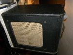
1950s Harmony 8418 tube amp rebuild

littlemerl

New member
Hi

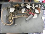
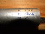
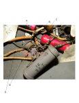
I'm working on this small 1950s Harmony guitar amp replacing all the capacitors and resistors to give it a fresh start. I haven't found a schematic for this amp so I'm looking at each component and writing down the values as well as testing the resistors as I go. I decided to cut open the cap filter can because I didn't know which value caps were where in the can and at the terminals. I found that inside the metal ribbons don't have any values on them so I am no further in understanding which new electrolytics I will put where. Here are the values in the can: 20 uf 450v, 10uf 450v and 50uf at 25v. If you look at the terminals (labeled 1,2,3) of the can inside the chasis and what wires and components connect to them can you decipher where the new electrolytic caps will go? Any help is appreciated.
Picture 1379.jpgPicture 1383.jpgPicture 1372.jpgFilter can tabs Harmony 8418.png

Info about labeled picture:
A: black wire comes from 6v6gt tube
B: yellow wire comes from different pin on 6V6gt tube
C:Terminal on filter can I labeled 2-all three resistors in the image connect to it
D:white wire connects from transformer to ground
E: white wire connects to 5Y3 tube
 
When you eventually get that multican electrolytic cap' out you should find that the square and triangle shapes are duplicated by the tags showing you which value went where.

If I had to guess I would say the 20mfd was straight to the rectifier and then to the output transformer. Then from that point the 3k R feeds the 50mfd section and the screen grid/beam plates. The 10mfd is further decoupling to the pre amp.

Note that the capacitor seems symmetrical so use a Sharpy to mark its orientation on the can and chassis.

Now, I don't know the safety regs over there but I doubt that single pole mains switch/VC would pass muster here! In any case I would get the transformer insulation tested before spending too much time and money since if the thing is a shock hazard it will all be wasted. I doubt you could find a replacement transformer for sensible money, if ever.

If you draw out carefully what goes where as you strip the amp (and all the caps at least need replacing) I am sure the schematic will become apparent. If not, post the drawings, I am sure I or someone like me can help.

Dave.
 
You could use a Champ schematic, or a Les Paul Junior schematic as a reference, and it won't be too different. You know the 20uF is the Plate filter, and the 10uF is the Screen grid filter. The 50uF is the 6V6 Cathode bypass capacitor.
 
OP: I have an old Wards amp I'm (eventually) restoring. I found an original Sams Photofacts schematic from a guy on Ebay. The amp had a nomenclature plate with the actual model number that cross referenced. It even has a picture with arrows pointing to every single part. That said, I'd defer to the other posters here!
 
Boy, I wish I had something like that, but luckily this is a pretty simple little amp with not many parts. I've already done this on a 60s harmony H304 that worked out very nicely. Thanks for the info about what caps should go where theoretically, and now that I can see the inside of the cap can the symbols on the metal tabs are quite clear. I never knew how the cap cans were constructed. I assumed it was just normal electrolytics inside of a can. About safety, I do plan on wiring a three prong plug before running it. I was wondering if I can check the integrity of the transformers with a multimeter or do I need someone to check it for me. I assume if the insulation was bad the coils would be shorted.
 
I'd Variac it up slowly, noting the current draw. A Champ fuse is what, 2A? If you see that at a 60VAC input or even an 80VAC input, you got problems. You can do it with the tubes out, and then again with the tubes in. If the amp makes a horrible 120Hz buzz, the filters are dried out. But you may be surprised, and they're good. I have seen it many times. The couplers are quite possibly leaky, so be ready to change those. If the resistors are cracked carbon, they've likely drifted all over the place. You can usually smell a bad transformer.
This is one of those fun projects that isn't too complicated, and makes a rainy Sunday go that much quicker. Well, it won't rain in December, unless you are down South. Even if you rebuild the whole thing, you're only looking at maybe 4 hours.
 
I have a Champ schematic of the 5C1, 6SJ7, 6V6, 5Y3 close enough for jazz? That uses a 2A mains fuse whereas later single stage Fenders use just 1A. I would guess the 5C1 was designed pre anti-surge "T" fuses and I would fit 1AT in there. The caps are all 8mfd 450V, 3off and a 25/25 6V6 cathode bypass. The 6SJ7 is a pentode, I don't have a Champ schem' using an octal triode but you could crib the 5F1 (12ax7) and change the cathode bias Rs accordingly.

Re transformer insulation. It is windings to frame, chassis, that is the danger. IF you fit a solid earth and no fuses blow it is probably ok but get the whole thing PAT certified as soon as possible.

If you want any of these
circuits, PM me.

Dave.
 
Back
Top