What about DIY pedals? Any "trusted" resources for kits?

pikingrin

what is this?
Tadpui's post about preamps got me thinking about shirking more of my household duties in favor of a fun project for once. I've become reacquainted with my soldering iron through my most recent guitar mods but it would be kind of cool to put a pedal between it and the amp that I had something to do with more than just pulling cash out of my wallet. I don't have a compression pedal (I've heard they're useful) so that would be an easy starting point.

Google pulled up a crap ton of sites that had DIY kits so I started browsing around on the first one up. BYOC (build your own clone) was top of the list and the prices, compared to a prebuilt, off-the-shelf unit, seem reasonable. Schematics and instructions are up on their site, too. But, the whole site looks kinda cheesy so I'm not really looking to pull the trigger just in case. Are there any other sites that anyone here have used in the past that should be considered reliable options for a relative beginner looking to up the ante?
 
Tadpui's post about preamps got me thinking about shirking more of my household duties in favor of a fun project for once. I've become reacquainted with my soldering iron through my most recent guitar mods but it would be kind of cool to put a pedal between it and the amp that I had something to do with more than just pulling cash out of my wallet. I don't have a compression pedal (I've heard they're useful) so that would be an easy starting point.

Google pulled up a crap ton of sites that had DIY kits so I started browsing around on the first one up. BYOC (build your own clone) was top of the list and the prices, compared to a prebuilt, off

View Discussions and Categories on The Fretboard

Lots of guys building guitars, pedals, modding amps da' bizz. All levels of experience.

I usually recommend beginners start with an amp based on the LM386 chip (our Maplin do a kit for it and it might be availably wwide as a Velleman kit) . Hit the chip with 3volts from a couple of AAs and it makes a splendid guitar headphone amp. Give it 9V, PP3 and it will put a watt into an 8 R speaker and make quite a respectable amount of noise. Very handy as a signal tracer/test amp.

Anyone want a bit of One on One they can PM me. I don't build pedals but should be able to help with general electronics problems.

Dave.
 
Last edited by a moderator:
I hang out at the diystompboxes forum quite a bit, and it's a great place to go with questions on anything having to do with building your own pedals. AFAIK, BYOC is pretty well respected. Maybe not great web designers, but I've never known anybody to complain about their products or their service.

GGG and smallbear are a couple other places that are well known and respected. I think most of these folks are actually active themselves at the diysb board.

I personally have never bought a kit from anybody, though I did make one order of parts from smallbear and the transaction went smoothly enough. I reference schematics from ggg pretty often, also.
 
I think that this would be a great project to prep me for a more complex build like a preamp. I've also looked at the BYOC and DIYstompboxes, they really look right up my alley. It'd be cool to build a fuzz or two just to see what the results would be.
 
Went ahead and splurged on an OD kit from BYOC. It comes with extra diodes which, from what I understand, give you the distortion, so I can play around with them a little and see what happens. Now to figure out what all the components do so I have a better idea of what I'm doing.

Should be here over the weekend but Saturday is opening day of deer season so I probably won't even open the box until next Monday assuming it arrives on time. Pretty excited!

I figure that if I spend time on this and study the schematics, I should be able to do another more advanced build from a schemo without a kit... There are a few types of pedals that just seem like they belong in my collection that would be fun to build myself. :)
 
Cool, let us know how it turns out.

Does the kit come with a schematic, or the very explicit "paint by numbers" instructions of "this exact resistor goes in this exact slot" directions? I'm such a novice that I'd need the latter. I'm not sure that I trust myself to read a schematic yet...
 
Cool, let us know how it turns out.

Does the kit come with a schematic, or the very explicit "paint by numbers" instructions of "this exact resistor goes in this exact slot" directions? I'm such a novice that I'd need the latter. I'm not sure that I trust myself to read a schematic yet...
Click the link and you can download all of the documentation for the kit for free.

pikingrin - Do you really want to know what all those parts do? Geofx has a series of "Technology of..." articles online, but unfortunately not one for that MXR/DOD distortion. It's very much like the middle part of the Tube Screamer, so reading that article might shed some light. I could probably write one up, but not RTFN.
 
Click the link and you can download all of the documentation for the kit for free.

Cool, I'll check it out and see how well I might be able to manage it. Looking at it now, that's right up my alley. Pictures and everything!

My main difficulty so far in handling electronic components is telling the colors apart on resistors. I don't think that I'm color blind, but those damn rings make me wonder. The gray and purple stripes don't look gray or purple to me at all!
 
Ash: Yes, I would like to have an understanding of what does what; the first build is a kit, the next (if this turns out ok) will probably be, too. But, I'd like to gain an understanding of it so I can figure out why whatever I'm doing does what it does. :) From my initial digging I have a menial understanding that diodes only pass signal one way. Resistors do what the name says - resist - so they don't pass as much. And transistors that have 3 legs that need to be connected right... Capacitors, if a certain type, can be wired either way. Outside of that, no clue. I've still got digging to do to see what does what; I'm really curious about the diodes for this particular project though. Experimentation will tell what does what when it comes down to it.

Tad: Not sure what it comes with as far as instructions go; I'm hoping that it's more than a schematic but I'm sure, with what I've seen on the google so far, that it shouldn't be too hard to figure out what goes where (and how to do it). This is probably the crappiest site ever but it helped a little to try and understand, a little bit more, what does what...and kind of how it goes together. More learning to follow...
 
Last edited:
Cool, I'll check it out and see how well I might be able to manage it. Looking at it now, that's right up my alley. Pictures and everything!

My main difficulty so far in handling electronic components is telling the colors apart on resistors. I don't think that I'm color blind, but those damn rings make me wonder. The gray and purple stripes don't look gray or purple to me at all!

Tad' do NOT trust the colours on resistors....Ever! There are in any case two current systems of coding, the 3 band and the 4 and even old "pros" like me find it hard to be certain.

However the key piece of kit any budding constructorist must have is a digital multimeter and so check each resistor before you solder in place.

On a big project I suggest a sheet of expanded polystyrene and a Sharpie then you can measure each resistor and stick it in the poly and mark it. Sound like a bit of work but nothing compared to the merry dance a wrongly fitted component will cause you!

If you like chaps I could post a very simple design process of a single transistor stage? This would I hope make plain the reasons for the use of resistors (and other components) and why their value is important in the point in the circuit they are used.

Tell me what you think?

Dave.
 
What we call audio signal is almost always measured in Voltage. Higher voltage (actually, wider swings) is what we call "higher level", or more volume. For the most part we never really need to worry about current, it just kind of falls where it must. Everything we do is to manipulate voltages, and we do that using a structure called a Voltage Divider.


Everything useful is a Voltage Divider! Learn how to recognize them and you'll be able to sort out anything.


They always work like this:
t_d_9801d.gif


Some input voltage is put across the two impedances, and the output is taken from the junction between the two. That output voltage will be related to the input by the same proportion as the "bottom" impedance to the total impedance. If Z1 and Z2 are equal, the output will be exactly half the input. As Z2 gets bigger with respect to Z1, the output gets bigger. In pure theory, the actual values don't really matter, it's always the proportion that matters.


The only question is what makes up Z1 and Z2. In almost all cases they are both actually made up of some combination of multiple components, some of which have static values, and some of which change based on things like frequency, input voltage, etc. But we can simplify things a bit to get our heads around it.


The most basic version is where both Z1 and Z2 are pure resistances - that is Resistors. These always have the same value no matter what you stick through them, and a divider made of pure resistances will attenuate all AC and DC voltage across them exactly the same.

Then we have some components where the value is dependent on the frequency of the signal.

In a capacitor, this value (called reactance) is higher for lower frequencies. At DC it is infinite - an open circuit - and at very high frequencies it's close enough to 0 - straight wire, a short. In between, it's in between ;).

If we put a capacitor in place of Z1 above (and leave a resistor for Z2), we get something looks a lot like this:
210px-High_pass_filter.svg.png

At low frequencies, Z1 looks really big compared to Z2, so those frequencies are attenuated. At higher frequencies, Z1 will be much smaller than Z2, so there will be less attenuation.

Swap them components around and you get this:
low-pass-filter.png

Which is a low-pass filter because Z2 gets smaller at higher frequencies, and causes more attenuation.

An inductor is pretty much the opposite of a capacitor - higher frequencies see more reactance. The filters built with them look very much the same as with caps, except high-pass becomes low-pass and vice versa.

We almost never use a capacitor or inductor for both Z1 and Z2, but when we do, it works pretty much the same. If you start mixing capacitors and inductors, you have to start worrying about phase angles and imaginary numbers and vector math. We're not going there today. You can kind of eyeball an RLC filter with what I described above to give yourself an idea of what will happen, but the specifics will be a bit different.

What about a diode? That's where the excitement is, right? How does that work into this voltage divider crap? Well, this gets a little weird, but I'll try to keep it simple. A diode can be thought of as a resistor whose value depends on the (attempted) voltage across it. When the voltage at the anode is greater than that of the cathode, the effective resistance of the diode decreases with greater voltage. If we replace Z2 in the original divider with a diode we get something that looks a lot like the clipping section in your OD/Dist pedal.
diode_clipper_1.gif

But this is where it gets a little weird. The output voltage depends on the equivalent resistance of that diode, right? But that equivalent resistance depends on the voltage. Makes actually calculating the voltage at that node pretty tough - you need recursive calculations or a W function. Let's skip that. The diode conduction curve works out so that it the equivalent resistance is very large (close enough to infinite) up until the the voltage hits what we call the diode's "forward voltage" threshold, at which point it will pretty much be exactly enough to hold the voltage at that level. A silicon diode has a Vf somewhere around 0.6V, so in this case (Fig2 in that picture), the signal goes through unaffected until it hits 0.6V, and then stays there no matter how much bigger the source tries to push it.

If you replace Z1 with a diode, you get a rectifier or a type of crossover distortion, but we're not going to worry about that until we start looking at Tube Screamers or compressors.

But wait! We're talking about Voltage Dividers, meaning attenuation, so how the hell do we ever amplify anything? Well, transformers can do it passively by converting current to voltage and stuff, but we're not going there today either. The thing about an active amplifier is that it actually divides a seperate supply voltage proportional to the original input signal voltage. That is, we build a voltage divider across the supply rail and vary one of the Zs dependent on the input signal. For these purposes, transistors and tubes work about the same, so let's look at a simple transistor amplifier stage:
2000px-N-channel_JFET_common_source_svg.png
In order to understand things, first we have to understand just a little bit about how the transistor works, but we're not going to get too far into it. Let's just suffice for now to say that as the voltage at G goes up, the resistance between D and S goes down. The divider we're looking at has RD as Z1, and the equivalent resistance from D to S as Z2 and is dividing down the power supply to create our output. So as the input voltage goes up, the D>S resistance goes down, and so does the output. As the input swings down, Z2 gets bigger, and the output swings up. Now, maybe that sounds like attneuation, but it's actually inverted amplification.

(Gonna blur some stuff here, folks who actually understand this might cringe, just understand this is sort of how it works, but not exactly)

Let's just say that an input of 0V is enough to make the transistor go to infinite resistance, and 1V is enough to make it go to 0 resistance. We have an input signal that is swinging from 0V to 1V and back. When it swings up to 1V, Z2 is 0, so the output is 9V * 0 = 0V. When it swings down to 0V, Z2 becomes huge with respect to Z1, to the point where we can say that Z1 doesn't really matter, so we've got 9V * 1 for output. As the input swings down from 1V to 0V, the output goes from 0V to 9V. It swings 9 times as far, but in the opposite direction. You can do the same thing with the transistor as Z1 instead and it will not invert, but it's far less common for a number of reasons, so let's leave that.

In fact, there's no transistor in the pedal we're supposed to be talking about anyway, so why do we care? Just so you can see that amplification comes from essentially modulating the power supply in response to the input signal. The opamp in your pedal is a collection of several transistors and some other components that do more or less this for us, and kind of hides that particular version of voltage division inside it's little black box.

How the opamp actually works is a bit more complicated, but here we have something not far off from a simple non-inverting opamp gain stage:
300px-Op-Amp_Non-Inverting_Amplifier.svg.png

Look at those resistors connected between Vout and ground, with the junction going to the -input of the opamp. Looks a lot like a voltage divider, no? Yes, it is, but it's in the negative feedback loop of this opamp. Without getting into too much detail, this is what I call Bizzaro World where everything is upside down and backward. Basically, as the feedback is attenuated, the opamp turns up the output to compensate. To gain of the stage (from Vin to Vout) is the inverse of the division from Vout to the -input. Please don't get confused by the fact that Z1 is R2 and vice versa. If R1 = R2, the divider ratio is exactly 1/2, and the gain of the opamp will be 2. As R2 gets bigger or R1 gets smaller, the voltage at -input gets smaller, so the gain goes up. As R2 gets smaller or R1 gets bigger, the -input voltage gets bigger, and gain goes down. You can (sort of) replace those resistors with other capacitors like we did in the filters above, and we end up with that Bizzaro experience again, the frequencies that would have been attenuated in the filter are instead amplified. The high pass (low cut) structure becomes a low boost, and the low pass (high cut) because a treble boost.

You may note that I didn't get into any kind of metaphorical mumbo-jumbo about water and pipes and tanks and blah blah because none of that really matters. It might be nice eventually to understand the physics of how and why a capacitor passes high frequencies more easily than low, but at this point all you really need to know to start reading schematics is the fact that they do.

I hope some of this helps somebody. I'll be glad to try to clarify any confusing points if you ask. I'll try a more specific dissection of the pedal you're building in the not too distant future.
 
Last edited:
Nice one Ash'. I know you needed to K.I.S.Sir but can I point out that it is almost always necessary to include output Z and load Z in any divider calculation?

A good example of this is an attenuator for guitar into (the unnecessarily high gain these days!)some AI inputs.

Dave.
 
There's a shitload of DIY pedal kits on ebay all the time. And completed DIY pedals people are selling with various names, too.
 
Ash, that's a great explanation, thank you so much. I printed it out so I can read through it again (and again); I really appreciate you taking the time to type that all out!

It'll make more sense when I get the kit and start digging through all of the parts. Dumb question though, in regards to diodes... One of the kits that I was looking at came with a few extra LEDs to "make the sound a little more nasty". I get that using them internally can do things to the signal; my question is more about the LED that is sticking out of the face of the pedal to tell you whether or not it's on. Does that color the signal as well?
 
Usually the indicator LED is not in the signal path. It just hangs off the power supply. Sometimes when the LED "turns on" it draws a lot of current all of a sudden, and there are a couple ways that can sometimes cause a pop or click in the audio, but no, it won't color the sound at all.

Course, some folks like to put their clipping LEDs somewhere they can see them. :) LEDs have different "forward voltage" thresholds than silicon. Red ones are usually right about double. What that means in practice is that they don't clip quite so early. The output will be louder and overall less distorted for a given input and knob setting. That might sound nastier to some folks.
 
Nice one Ash'. I know you needed to K.I.S.Sir but can I point out that it is almost always necessary to include output Z and load Z in any divider calculation?

A good example of this is an attenuator for guitar into (the unnecessarily high gain these days!)some AI inputs.

Dave.
Just noticed this. I did say: "The only question is what makes up Z1 and Z2. In almost all cases they are both actually made up of some combination of multiple components..." ;)

K. So I can't really link to the schematic for your specific kit, but it really is a basic clone of the DOD 250 with provisions to convert it to a MXR Dist+. They're about exactly the same circuit, only a couple of component values are different. That doesn't change what they do or why they're there, though they might have some effect on the ultimate outcome. It's actually quite a bit like a Rat also, but...

Here's a scheme for the 250 with numbered components to make it a bit easier to reference. I'll try to identify any places where this differs from the BYOC kit, but again I think we're talking more about how and why more than exactly how much.
dod250-schem.png

Neither this nor the BYOC schemes include the actual bypass wiring. That's not unusual. I'm pretty sure that it's a simple true-bypass arrangement on a 3PDT, and we're going to ignore it for this discussion. The above scheme doesn't include the power supply switching that you can at the input of the BYOC schematic. This is the ubiquitous way of disconnecting power when the input cable is unplugged. The "bottom" of the battery doesn't actually connect directly to "ground" to complete its circuit and do its thing. It goes to the ring of the TRS input jack. When you stick a regular TS guitar cable in there, the ring terminal touches the shield, which connects it the whole thing to ground and completes the power supply circuit. Note that this circuit is always on as long as it's powered and a TS cable is in the input, regardless of bypass status. The bypass switch just disconnects the input and output of the circuit, doesn't turn the thing on and off. It does turn the LED on and off, but...

The tip of the input jack goes to where it says In on the schematic. :)

R1 is not on the BYOC schematic, but is actually a good idea. It is called a "pull down" resistor and can help keep it from popping when the switch is flipped. See here for more detail than you probably need on that.

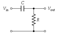
The BYOC does have an optional capacitor in that location. That's the "bottom half" of an RC LPF like in my post above. The "top half" is pretty much the guitar or whatever else happens to be plugged in. I think this is a very small capacitor so should work out to a very high cutoff, and shouldn't much affect the range of frequencies that normally come out of a guitar. A cap in this spot is usually there to filter out ultrasonic and radio frequency noise which you might not even actually hear, but could eat up headroom and generally make the circuit act funny. Then again, it might be enough to hear. Who knows? To calculate the cutoff we need the specifics of the input, which could be anything at this point, so... Try it and see if it makes a difference to you. If not, I'd highly suggest putting a 2.2M resistor in that spot as a pull-down.

C1 creates a high pass filter, but it's a little complicated to see what the "bottom" of that filter is because it includes R2, R3, R8 parallel to R9... Anyway, it is a relatively large capacitor over relatively large resistances, so its cutoff is going to be relatively low. It may not even touch the fundamental of the low E, but it might roll off some from the bottom end of a bass guitar or drop tuned/baritone guitar. I don't think this cap is really supposed to affect the tone, though. It's real purpose is what we call "AC coupling", but is easier understood as "DC blocking". We want to let the AC audio signal through this node, but we don't want any DC voltage from the input to mess up the way our circuit works, nor to let any DC voltage we apply to get out to the outside world or to be affected by the input end of the circuit at all. The input side of this cap should be wiggling up and down around 0VDC, but this cap means it really kind of doesn't matter because any DC offset gets stripped out anyway.

R2 does create a voltage divider with R3, but if you do the math, you'll find that it's really an insignificant amount of attenuation. What it more does is limit the current into this node and it's kind of more "best practice" than important part of the operation.

R3 is important and interesting. Remember, we stripped off any DC that might be on the input, so it should now be wiggling around 0V. Remember also that this opamp gain stage is going to do its thing by dividing the power supply proportional to the input. Well, it may or may not be obvious, but the output of the opamp can't swing beyond the extremes of that power supply. That is, the highest it can go is 9V and the lowest is 0V. It can't swing more negative than the power supply's most negative voltage. (Most opamps, including the one you're using, won't actually go all the way to either power rail, but that's not super important right now) So, you want to amplify a signal that sometimes swings below 0V, and actually want the output to go even further below 0V, but it can't go below 0V at all. We need to get the input signal to swing somewhere in the middle of the power supply so that there is plenty of room for the opamp to amplify both upward and downward swings. We add a voltage equal to almost exactly half the power supply, what we call a "bias voltage", which is what that "VB" at the other end of the resistor means. That node will be connected to the other spot that says VB up by C7, and even though we're getting out of order, I suppose it's time to look at that power supply chunk.

Let's start where it says +9V(T). Don't know what (T) means, but this is the "top" of the battery and/or the positive terminal of the DC power connector or just generally the most positive point on whatever we're using to power the thing. R7 is kind of a current limiting thing which keeps helps keep the capacitor from sucking too terrible much current when it's first powered up. It is also the "top" of a low-pass filter which has C6 as its "bottom". That cap is really big, and even though this resistor is pretty small, it still works out to an extremely low cutoff frequency. The amplification happens by dividing the power supply in response to the wiggles of the input, so what do you think happens if the power supply is already wiggling on its own? Yep, you'll hear it! If this is powered by a battery, it's not going to be wiggling, but if you're plugged into a wallwart it could be for any number of reasons, so here we're filtering out as much AC signal as we possibly can to get a nice flat, quiet DC supply to work from. Any parts that need to connect to 9V wants to connect after this filter, and that's the VA point. In this case, it goes to the positive power supply input on the opamp.

Now R8 and R9 are a picture perfect example of the basic resistive voltage divider. Depending on which version you're building, they will be either 22K or 1M, but in either case they match, and you'll recall that this means that the voltage at their junction (VB) will be exactly half of the supply voltage, which is what we want for our bias voltage. In actual fact, the choice of values here is almost arbitrary as long as they match (remember proportion is all that matters in a divider) and are much larger than R7. The smaller resistors will make the whole box pull a bit more current from the supply, but I'd be really surprised if you actually hear a difference.

Especially since they are pretty much bypassed for all audio frequencies by C7, which is another really big cap meant to filter off any AC signal that might have got through the last filter, or generated in the resistors, or brought here through R3. Any noise at this point would be coupled into the input and be amplified along with our signal, so we want to make damn sure we kill it dead before it can get there.

And then we're back to the non-inverting (+) input of the opamp. This part of the circuit is really not that far off from the non-inverting opamp example I posted above. Ignoring the caps for just a minute, the feedback is divided down with R5 as the "top" and R4 + whatever the Gain pot is set to as the "bottom". When the gain pot is all the way down, the full resistance of 500K is there. The divider is 504.7K/1504.7K, or about 1/3 of the voltage from the output is reaching the inverting input, so the opamp will apply about 3 times (like 9-10db) gain to the output. When gain is turned all the way up, it goes toward 0 Ohms, so the divider is 4.7K/1004.7K, about 1/200, so gain is a pretty hefty 200 times (something like 45-50db). Or at least it will try. Even moderate pickups can put out 1V peak to peak on harder strums, some hot humbuckers can hit 4V or more, and active pickup systems can get close to 9V or even more. Multiply even a 1V input (biased at this point to swing up to 5V and down to 4V) by 200, and you're asking the opamp to swing up to 104.5V and down to -95.5V. We already said it can't get bigger than 9V or smaller than 0V, so we end up "hitting the rails", clipping, distorting, right here at the opamp. The Dist+ has a 47K at R4, which makes for about 1/10th the gain at the max, but doesn't change the minimum quite so much.

But of course we can't really ignore those caps. C3 would be left out if you're doing the Dist+ version. It's a little weird to see the filter that it makes because it's got that resistor parallel to it, but lets pretend we just take that out. The divider is now C3 as the top and R4 + Gain as the bottom. At high frequencies, this cap is a straight wire, the divider doesn't (ratio very close to 1), and so those frequencies get through at unity gain. At low frequencies, C3 looks like a big resistor, so those frequencies are divided down more and more, and so the opamp will add more and more gain at lower frequencies. But then that R5 in parallel kind of won't let that equivalent resistance get too big, so the gain shelves off rather than heading toward infinity at low frequencies. The cutoff of this filter depends on the Gain control. I'm not going to calculated it, but usually will above the range of the guitar if not the audio range altogether when the gain is way down, and will maybe start to shave off a little bit of the top end when it's cranked. This can help tame some of the harsh fizziness at the very top end when it distorts hard, but almost as important is that it keeps it from amplifying any of that supersonic/RF noise that we tried to filter out but might have snuck back in since.

That low boost filter wouldn't be able to go to infinite gain at low frequencies even without R5 to shelf it off anyway though, because C2 is sitting there making the "bottom" of the resistor look really big at low frequencies. This cap does a couple other things, too. First, remember that this whole thing is biased up to wiggle around 4.5V, and if we connected that directly to 0V ground (at the other end of the Gain pot), it would just plain mess everything up. C2 blocks DC current via that route, so that this thing can work at all. It also creates a low-pass filter on the feedback with R5 as the top. R4 and the pot make it into a shelving low-pass by making sure there is some resistance in the bottom of the divider even at frequencies where the cap is a straight wire. Of course, we're here in Bizzaro World, so the frequencies that get attenuated here actually get more gain at the output. So, it acts like a high boost. The lower frequencies get through at unity, and higher frequencies get more gain. Again, I'm not going to calculate the cutoff here. It is somewhat dependent on the Gain knob again, getting higher as the gain increases, and at high settings it probably creates a pretty significant drop across much of the lower end of the guitar range - even into the what we might call "low mids". This is important in making it sound like an overdrive or distortion rather than a fuzz.

Then we're done with the opamp, and come out the output at the tip of the triangle. C4 is there for about the same reason as C1 - to strip out the bias voltage we've applied and get things wiggling around 0V before we pass it down the road, and to keep DC conditions on the output from messing up the opamp action.

R6 is partly there to limit the amount of current that can be pulled out of the opamp, partly to help alleviate some of the weird things that capacitance (like the output cable) can cause when connected to an opamp output, and mostly to work as the top of the low-pass filter with C5 (reduces some more of the harshest distortion byproducts) and the clipping divider made with the diodes. The DOD 250 has one diode (D1) pointing one way and two in series (D2 and D3) pointing the other way. When the signal swings up from 0V, the resistance of D1 starts out near infinity and gets almost not at all smaller until it hits about 0.6V where it rapidly goes around the curve of the exponential function and then pretty much stays exactly enough to keep that voltage at 0.6V no matter how much more positive the opamp tries to make it. When the signal swings below 0V, the same thing happens through D2 and D3, but it doesn't turn over until it has gone twice as far. It clips at -1.2V or so in this direction. That causes a bit of asymmetry in the distortion which will give us some even order harmonics and sound a little more "musical" to some people. In the Dist+, there's just a single diode on that negative side, so the distortion is symmetrical, so maybe a bit nastier. It will also be a bit quieter at the output, because the signal can only be 1.2V peak-to-peak rather than 1.8V. I would suggest that you could put a red LED in place of both D2 and D3 and it would do about the same thing. Some folks claim to be able to hear the difference in "clipping characteristics" between an LED and a pair of silicon in series, but it just can't possibly be more than extremely subtle.

Then you've got the Volume pot. If you imagine that squiggly line that represents the resistive element as being split into two resistors with their junction connected to the wiper, I think you see how this is pretty much a textbook example of a simple resistive divider. Turn it up so that the top resistor is 0 and the bottom is 100K, and you get a ratio of 1, no attenuation. Turn it down and the bottom resistor goes to 0 with the top at 100K, and you get a ratio of 0/100K = 0, and the output is silent.

This really is a super simple, but very versatile circuit. You should build a Rat next.
 
Wow, lots more info and a few options thrown in there... I may splurge on a breadboard to throw this stuff together on before soldering it all up to the PCB, especially for the R1 resistor instead of the cap like you suggested. I'm interested in hearing what the difference would be between the two just in case one sounds "better" (subjective) than the other.

Thank you, again, for all the info on this, Ash - tried to give you rep but I've got to spread it around a little first... Getting excited for this stuff to get here so I can start tinkering!
 
Oh hell, what else am I going to do all night at work? ;)

I honestly spend more time reading and thinking and writing about this stuff than I do playing with it. I've built a few different pedals that I'm pretty happy with, but lately I've been "working" toward going all digital. I've been analyzing circuits more with an eye on how to emulate their behavior.

I very much encourage you to grab a breadboard and play around with changing values and try different things. There is nothing in a 9V stompbox that is going to hurt you or start too terrible big of a fire.

You absolutely need a decent multimeter. I'd suggest a reasonable digital model with at least DC voltage, resistance and capacitance readings. Look at the specs and try to get the highest impedance you can find. Some of the things we work with have pretty big impedances, and we need the meter to be significantly larger so that it doesn't influence the readings too much. 10M is probably good for most things.

Edit - Also, get some alligator clips. And grab a spare capacitor and cable and build yourself an audio probe.

If you're at all interested in studying circuit behavior without the actual hands-on fiddly part, I'd recommend grabbing a Spice modeling software that will allow you to draw up schematics and analyze frequency response and transient response and all that kind of stuff. The free version of 5Spice is really great and easy to use. LTSpice (no relation) is a bit more powerful and flexible and will let you load in a .wav file and process it through the modeled circuit, but that function is really slow and it's a lot less user friendly in general. Dude over at DIYSB has created LiveSpice which supposedly lets you play audio through the modeled circuit in real time and I think he was working on having it compile to actual VST plugins you can load up in your DAW. I still haven't gotten around to trying it, despite being pretty excited by the prospect.
 
Well, I've got 2 different MMs, an analog and a digital - both cheapies from Lowes. Having said that, I don't know if either of them measure capacitance... I know DC voltage and resistance for sure, but capacitance? I dunno. Same goes for the impedance, not sure. I've got plenty of gator clips, too - got a bulk pack when I was working on that guitar. I'm going to go to radio shack tomorrow to see if they've got a breadboard, I'll grab a capacitor while I'm there so I can put that probe together.

I just brought the kit in from the mailbox (out of town all weekend) and side by side with the instructions it looks like a fairly simple build. I'm going to lay it all out later this evening and might start soldering...
 
Back
Top