Stupid question regarding stereo input jack for DIY pedal...

pikingrin

what is this?
Probably stupid, I can't find an specific yea or nay on it though...

Before thanksgiving I put together a treble boost kit from GGG and, upon plugging it in and powering it up, when the pedal was bypassed there was a signal to the amp. When the pedal was engaged the no signal passed through. I've been in and out of town since then and have just started to troubleshoot - building my audio probe tonight or tomorrow morning so that's in the works.

Tracing through the "schematic" that I got from GGG, it appears that all of my connections are made in the right places, soldering is shiny and clean (much better looking than the first pedal I built that actually works) and I'm running out of ways to check what's wrong (until audio probe is complete).

All that being said... One thing that I did on both builds was forego the battery terminal installation between the input jack sleeve terminal and the DC power supply jack terminal. My brain says since pedal 1 worked without it then pedal 2 should as well but I'm trying to double check my reasoning - I'm human and I've been wrong in my assumptions before... Is that an accurate assumption in this case though?
 
You're meant to wire battery negative to the socket ring instead of shield so that ground connection is only made when an unbalanced plug is put in and the battery can't drain when not in use, right?

Leaving out that battery clip shouldn't make any difference to you as the DC9V socket supply would be permanently grounded anyway, as would input shield.
I take it you're testing with a 9V wall power supply?

Share the schematic and some pics of your project, if it's handy. :)
 
You're meant to wire battery negative to the socket ring instead of shield so that ground connection is only made when an unbalanced plug is put in and the battery can't drain when not in use, right?
Yes, that's correct - battery terminal goes to the "ring" connection on the stereo plug so that it doesn't make a connection unless a cable is plugged in to the input jack.

Steenamaroo said:
Leaving out that battery clip shouldn't make any difference to you as the DC9V socket supply would be permanently grounded anyway, as would input shield.
I take it you're testing with a 9V wall power supply?

Share the schematic and some pics of your project, if it's handy. :)
Yep, I've got a standard wall wart PSU for boss/ibanez pedals (9v, negative ground) that I use for testing. The first pedal, an MXR Distortion +, worked perfectly - looks like a turd but works some magic on the tone. This one goes silent when engaged. Pictures may not help but I'll attach some - ignore the jumble of wires, I have pulled them all out of place going through the build sheet tracing circuits and checking my connections so it looks like a rat's nest in the pics.

Build sheet can be seen here, it's a pdf.

And, here are some pics...
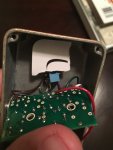
This one shows the rigged up pot cover - a piece of cardboard to keep the solder joints from making connections with the pot. I got this kit with a small enclosure and there's not any good way to make use of the standoffs they send. I'm worried about this because I powered it up and tried it before I even thought of putting any kind of non-conductive materials between the board and the pot - I'm sure that any and all of the solder joints in the vicinity of the pot were touching when it was powered up. Hopefully nothing got shorted and fried but the audio probe will probably be the only way to figure that out.
liftedboard.JPG
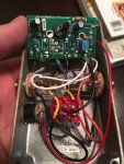
This is a decent view of the board - all resistors/capacitors were triple checked for values and functionality prior to installing.
openbackupboard.JPG
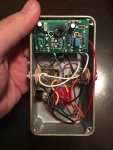
This is just an alternate view of the board and layout internally. Again, the wires look like a jumbled mess...I had them tucked away nicely when I put it all together but in my troubleshooting they have all just been pulled out of place.
openback1.JPG

Hopefully this book isn't too long to read; thanks for taking the time to look over this mess! :)
 
No worries. Does the LED come on? If not, test the soldered points on the DC jack with your meter for 9V, noting polarity.
Maybe the picture isn't showing it well but it looks like the solder's pretty heavy there. Maybe they're bridged?

If you're worried that something got shorted and fried during your first test, the transistor would probably be the first thing to check.
Do you have a meter that'll test transistors or do you have a spare to switch in?


Something else that took my eye. The base leg of Q1 has two traces meeting at it - You've soldered to one of them.
Is there continuity between these two points. It's hard to tell from the photo and the schematic.
 
Last edited:
The LED does come on, yup. I guess it would be a good idea to mask that solder joint just in case, too; I'll throw some tape over it.

As far as the transistor goes; I've got 2 MMs, a digital and an analog, but I'll have to do a google search to make sure one of them has the capability to test transistors. The traces, though, are bridged and there is continuity between the two.

I noticed, as I was going through more last night, that I connected the wire going to A on the board to a neighboring opening. Continuity between the 2, there are actually 3 connection points in line on that trace, so I doubt that could cause a problem...but maybe it could? I'll move that to the proper point just for the sake of making it "right" per the build sheet.

Out of ideas, off to make my audio probe and getting to the fun part...
 
I noticed, as I was going through more last night, that I connected the wire going to A on the board to a neighboring opening. Continuity between the 2, there are actually 3 connection points in line on that trace, so I doubt that could cause a problem...but maybe it could? I'll move that to the proper point just for the sake of making it "right" per the build sheet.

Funny I spotted that first and thought it was the problem, then realised those three points are bridged so, no, it should be cool.

Probing it is a good idea and if you get nothing anywhere on the board maybe just remove the switch temporarily and have input/output hardwired for testing?
I would try a different transistor to rule that out, since you're confident enough that you shorted some stuff. Since it's socketed and easy to switch, you may as well.
 
Yeah, I need to get one though - I have no spare transistors. Resistors and caps, I've got, toggle switches, too. No spare transistors... :o

I should have some time to head over to radio shack; I think they might have them, and I'll swap it out if I find any. If not, it'll be a few days to get one shipped over. Thanks again, Steen; appreciate all the help!
 
Quick update... Transistor is good. I pulled it out and tested it, thank you google, and it functions properly. Time to get probing.
 
Ok, cool. Good to know.
An other thing you can do is continuity test the input path.
Plug in a cable and test between tip and the input point on the board. If you don't read 0 then there's something wrong in your routing or with the socket/switch/whatever.
Do the same with output from board output point to tip of plugged in output cable.

At very least that'll prove your ins and outs before you spend time probing. :)
Ok, so I checked the signal to/from the jacks and that's kind of got me confused a little bit. Still green at the components so I'm researching how the switch functions so I can get an idea what pins are actuated or shut down and understand the signal path through there. I know my wires are in the correct place on the switch - per the build sheet - but that seems to be where the shutdown is.

From the input to the switch, without having power to know if it is in the on or off position, I get a signal from the tip of the plug to 2 pins of the switch - 1 is where the wire from the jack connects and then one adjoining pin that traces to the middle leg on the volume pot. When I check any of the wires that go to the board I get nothing. From what I can tell, there's not even a signal getting to the board - seems that I need to replace the switch and see if that does anything since it's wired correctly - again, per the sheet. I get continuity between the middle pin on the switch and the board but not from either jack to the middle pin regardless of switch position. I'm pretty sure, typing this all out, that I've become more confused. :D

New switch hopefully tomorrow and I'll double check all my connections when I pull the guts out to desolder everything that needs it. At least I've successfully snapped my LED leg from the board! :laughings:
 
Ok. Try to understand the switch fully before proceeding.

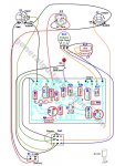
The orientation in your pictures is the same as in the schematic, so that's handy.
The switch takes the middle row of pins and sends them all to the top row, or the bottom row.


In the bypass position the middle row is tied to the top row.
Pedal input (Green) get's grounded to the black beside it, via that jumper on the top row.

Your guitar input (bottom left) isn't sent anywhere by the switch, hence that yellow bridging wire.
That arrives at top right which, because of the switch, is sent straight to output tip orange.


In the ON position the middle row is tied to the bottom row.
Pedal input green is tied to guitar input, so you should be getting GTR to the board. That yellow bridging wire does nothing now.
The jumper above them is connected to nothing.
The LED gnd pin is connected to ground on bottom row,
and the pot wiper blue, which is your board output, is tied to orange, output jack tip.

Hope I didn't trip over my words there....lol.

Basically, the switch should either send your input signal to Green (on) or Orange (off)

Screen Shot 2015-12-11 at 01.05.12.JPG

Do the same with output from board output point to tip of plugged in output cable.

Oops. Should have said this will only work with the volume turned up.
 
Last edited:
Crazy thought... If I, say, mixed up 2 capacitors...could that cause it to go dead when switched on? I did not have a magnifying glass and the parts list was vague. I may have put the 0.0047uF cap where the 0.047uF cap was supposed to go and vice versa. They were both small and the labelling was smaller than my eyes could make out (I have since invested in a magnifying glass). I put the smaller cap where the smaller value was in hopes that it was logical to assume that there was a correlation between size of cap and the value of it.

Thank you, again, for the info - that explanation makes sense of it all, really. Makes me feel kinda bad for not knowing anything about anything to help you out with that organ PSU and all that. :o The knowledge is much appreciated!!
 
If you got the polarity wrong on the electrolytics it certainly could, but they look correct.
I don't know if you received the parts from them as a pre-assembled set or not, and I can't read the values on your electrolytics,
but I did notice that they have a blue cap and black cap where you have the reverse.
You've seen this, yes?
Double check the values on those two.


The other caps look to be right. I can make out 1nk and 6n8. The two ceramics I can't tell from the pics so, again, worth verifying.


Now that you've the switch sussed, do that continuity test from the tip of a plugged in input cable to the input point A on the board.
If you don't read 0 with the switch on, there's no signal even getting to the board.

That PDF also lists ballpark DC figures that you should read on transistor BCE.
Give or take a little, especially if your battery voltage reads low, but you should see a very similar pattern.
Read between DC negative and DC positive,C,B,E - Four readings.
 
You've seen this, yes?
Double check the values on those two.
You know, I looked over that before I started populating the PCB but never made reference to it once I had the build sheet printed. Fairly certain I got C8 and C2 backwards so I'll fix that.

The electrolytics are both correct values, the colors are different though - the ceramics are definitely backwards. Radioshack did not have the switch I need, this one is definitely bad, so I am going to have to wait for one to ship. In the meantime I'll get the improperly placed caps corrected and check those voltages through the transistor. Hoping to have this thing sorted out before Christmas! :thumbs up:


Cool..Ok.
A few things. Ceramics can't go backwards. They're not polarised. Ie, there's no positive and negative.
Electrolytic and lesser common tantalum capacitors will have a positive and/or negative marked so you must fit those the right way around.
You have done with your two lytic caps as far as I can tell.

The switch. How are you sure it's bad?

If you call the pins

1-2-3
4-5-6
7-8-9

One way should join 4-7,5-8 and 6-9
the other should join 4-1, 5-2, 6-3

Connect your meter in continuity or resistance setting to pins 1+4 then operate the switch.
Reading should alternative from 1 to 0 and back as you flick it.
Same test across 2+5,3+6 then 4+7,5+8,6+9.
The only time I've seen switches like that fail they've just fallen apart.

Heh...make sure it's not 90 degrees out....sideways. ;)


BTW, I'm a noob level tinkerer myself. Pinch of salt, and that.
Hope you get it sorted for Christmas too. I made a similar one and built it in to my little deacy amp. It's a very cool setup!
 
Last edited:
Back
Top