evm1024
New member
Well this is the first installment in the DMP3 mods project. As you may recall Antichef gave away his DMP3 and I was the one to win it (Super thanks again!). I wanted one to take apart and see what could be done to make a great pre better.
The first step has been to get a schematic. Of course none are available to be found on the net (at least for me) so as expected I traced out the circuit visually and hand drew it.
Here is a link documenting the effort.
http://arafel.org/audio/diy/DMP3/
So far we have a parts list and the schematics for the INA163 input amp, the gain selector / 75 Hz hi pass filter and the output stage.
Later I'll add schematics for the meter section and the power supply. In addition a little commentary on the circuits.
Lots of thought for mods to explore. Changing the PS is "easy" if you don't mind changing the case form factor. Other options are to change the 75 Hz (72 Hz actually) hi pass filter to be a complex filter to get a more colored sound. Then you could just change out some parts and drop some to try to get the most gain-on-a-wire. lastly changing the meter ro give more VU like results might be useful.
Regards, Ethan
PS if anyone want to to put this into a schematic capture program please feel free (and copy me)
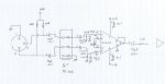
Here is the input stage for a sample (make that a TRS rather than a TS jack)
The first step has been to get a schematic. Of course none are available to be found on the net (at least for me) so as expected I traced out the circuit visually and hand drew it.
Here is a link documenting the effort.
http://arafel.org/audio/diy/DMP3/
So far we have a parts list and the schematics for the INA163 input amp, the gain selector / 75 Hz hi pass filter and the output stage.
Later I'll add schematics for the meter section and the power supply. In addition a little commentary on the circuits.
Lots of thought for mods to explore. Changing the PS is "easy" if you don't mind changing the case form factor. Other options are to change the 75 Hz (72 Hz actually) hi pass filter to be a complex filter to get a more colored sound. Then you could just change out some parts and drop some to try to get the most gain-on-a-wire. lastly changing the meter ro give more VU like results might be useful.
Regards, Ethan
PS if anyone want to to put this into a schematic capture program please feel free (and copy me)
Here is the input stage for a sample (make that a TRS rather than a TS jack)

")
") ) had plenty enough gain for me -- I'm not "analog only", though. Anyway, I don't need any more gain, personally
) had plenty enough gain for me -- I'm not "analog only", though. Anyway, I don't need any more gain, personally 
