DIY Reference Monitors: How to solder for DUAL connections?

I'm building a pair of single-driver reference monitors (poor man's Auratones). I want to be able to feed signal to them two ways:

1. by standard hi-fi speaker wire, red-and-black spring clips mounted to the speaker's back
2. by 1/4" mono TRS jack mounted through the speaker's back​

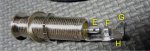
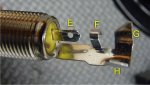
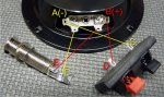
I've included pictures, and have labeled the various potential solder points.

If I were just using the red-and-black spring clips, I assume the wiring would run:
C ----> A
D ----> B
Correct me if I'm wrong (duh).​

I'm confused about how to include the 1/4" jack. 'E' is obviously a solder point, but shouldn't there be a second solder point - F, G or H?
And...I don't know which wire--red or black--goes where on the 1/4" jack.

Please tell me how to wire this so I can drive the speaker by both the speaker wire clips and the 1/4" jack.
If you put it in simple terms like "C to E to A" I'll understand.
Thanks
 

Attachments

  • all.jpg
    all.jpg
    64.2 KB · Views: 6,080
  • qtr1.jpg
    qtr1.jpg
    41.5 KB · Views: 409
  • qtr2.jpg
    qtr2.jpg
    34.5 KB · Views: 415
F is the sleeve solder point and G/H are clamps for holding your cable in place.
Often there is no F and instead there's just a small hole.

For one input or the other, wire

A-F
B-E

or
A-C
B-D


If you put them in series like this

A-F-C
B-E-D


then you'll have the choice of inputs, but ideally you'd want to use a switching jack socket, rather than the pictured one, so that your two sources don't ever become connected together.
A switching socket would disconnect E-D and F-C when a jack is present, see?
When a jack isn't present, the socket just bridges the gap for you.
 
Last edited:
Steenamaroo ==

Thanks for your helpful reply. There a lot of "letters" floating around here, so it's possible for information to get jumbled. That said, let me ask for clarifications:

1. I want to avoid wiring anything out-of-phase, so I'm paying extreme attention to which terminals attach to which. It may be hard to see, but the terminals on the speaker frame designate terminal 'B' as red. And of course, the 'D' spring clip connector is red. So I'm assuming the "red" signal will pass from 'D' to 'B' ultimately (correct me if I'm wrong).

If that's correct, the question is: Which terminal on the 1/4" jack is correct for the "red" signal. E or F? I only ask because your comments above are slightly inconsistent (a typo, or just too many letters floating around, ha). Would it be D--E--B or D--F--B? 'E' and 'F' are the 1/4" jack terminals.

2. I don't intend to use coaxial cable inside the speaker. The enclosure is very small so I want to connect the 1/4" jack using regular two-wire hi-fi speaker wire (one bronze metal wire, one white metal wire). Assuming I run the "bronze" wire to all three "red" terminals, can I just solder the "white" wire to all three "black" terminals?

3. I don't have a switching socket as you suggest. I had to order these parts online and will have to make do with what I have on hand. I'll be careful to never attach the speaker by both methods simultaneously, so am I safe using the parts I have?

4. A DIFFERENT APPROACH, MAYBE BETTER:

The speaker appears to have two 'A' terminals and two 'B' terminals (see 1st pic). Instead of wiring things in series, could I just wire the spring clip directly: D--B (red) and C--A (black) and then wire the appropriate 1/4" jack terminals directly to the other two A and B speaker terminals?

I think Option 4 might be best IF I can do it using speaker wire, and if you can confirm which jack terminal is "red" to keep me in-phase.

Thanks
 
Hi there,

You're right, my two options were inconsistent. I've fixed it now.

The phase (polarity) doesn't really matter, as long as you wire both speakers the same way.
It would matter if you were using other sets of speakers at the same time, of course.

With 1/4" jacks the outer part (F) is always shield/ground and the inner connector (E+jack tip) is always the conductor.
Generally black = sheild/ground and red = signal conductor for other types of wiring.

You'll probably find your speaker terminals are marked + and -.
Plus = red = tip and Minus = black = sleeve/ground/shield.

(Edit, looking closer I can see the +and- on your speaker.)


RE "4: A different approach" - What you describe is parallel wiring instead of series but it still doesn't address the issue of two input sources being connected together.
If you make a point not to connect jack and speaker wires at the same time then yeah, you'll be fine.
Like a lot of things, though, you only get to do it wrong once.

Here's a "diagram" showing the benefit of a switching jack.
Whether the jack is connected or not, only one input device is ever physically connected to the speaker, see?

Screen Shot 2019-04-04 at 18.04.58.jpg
 
Last edited:
Thanks, Steenamaroo (and gecko zzed, too) ==

So this is what I'll do, wired in PARALLEL (if I'm wrong, TELL ME NOW :eek:)

Spring Clips
RED(+) D to speaker B1
BLACK(-) C to speaker A1

1/4" Mono Jack
RED(+) E to speaker B2
BLACK(-) F to speaker A2


Thanks for excellent clarifications, and yeah, I'm all too familiar with your caveat, "...you only get to do it wrong once." :facepalm: Let's see how my luck holds in this instance. :D
 

Attachments

  • all-wired.jpg
    all-wired.jpg
    67.7 KB · Views: 88
In short, it's not a good idea to have two input options wired up without some kind of switch but, if you're going to, ^ that's a fine way to do it. ;)

If you change your mind, you could use a DPDT switch for safety instead of a switching jack.
If not, you're set. :)
 
Rather than have 4 wires going to the speaker it would be far more elegant to simply wire the spring terms and jack in parallel then take a single red&black to the speaker.

I also strongly urge you to use push on "receptacles" for the speaker connections. Note, some speakers, Celestions are 5mm tags, others 6mm. For a one off job you don't need a crimp tool, you can use pliers or a small vice.

Dave.
 
Rather than have 4 wires going to the speaker it would be far more elegant to simply wire the spring terms and jack in parallel then take a single red&black to the speaker.

I also strongly urge you to use push on "receptacles" for the speaker connections. Note, some speakers, Celestions are 5mm tags, others 6mm. For a one off job you don't need a crimp tool, you can use pliers or a small vice.
Thanks, Dave ==

I want to be able to remove the back of the speaker cabinet (the whole thing is roughly a 6.5" cube) so I'm attaching it with screws. I figured it would be a good idea to be able to separate the back from the rest of the unit entirely, so the wiring is as follows:

The 1/4" jack and spring catch connectors are mounted to/through the removable back panel.

1. 1/4" jack and spring catch connector red wires twisted together

2. 1/4" jack and spring catch connector white wires twisted together

3. Paired red+white wire from speaker

I'll use a small wire nut to join the back-panel red wires to the speaker red, and a second wire nut to join the back-panel whites to the speaker white. If I need to open it up for repair, I can simply remove the wire nuts and pull everything apart.
 
Back
Top