Tascam 388 insanely hot resistor help

jon83

New member
Hi all,

Sweetbeatz has been helping me the last few weeks with getting my 388 back in order, but he's advised me to start a new thread with a new problem that it's developed.

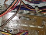
I've had problems with the motor engaging. Reflowed all the joints around power, servo and mother boards, which sorted the motor no starting problem, but I've now noticed a resistor on the motherboard that is getting insanely hot. I smelt burning before I reflowed the solder but figured it was to do with the motor issue, but it's this resistor. I've put a picture of the one in question below, it's on the right side of the mother board, right next to the transformer.

It's also developed a problem of rewind and fast forward being real slow. The motor problem I had was intermittent, so when it was working the ff and rr worked fine, it's only since I've put it back down flat that theres been an issue. I've tried adjusting the servos but no joy. It's like they start normally when I press rewind, but the rollers lift up like they do when you use return to zero, to slow the tape before it stops. It still plays, records etc fine.

Any help would be massively appreciated! Sure it's something stupid I've done when I was fixing it, but your own stupid's hard to spot.

IMG_3583.JPG
 
Last edited:
I can't help you with the underlying cause, but is that thing actually a capacitor at all? It seems to have 4.7 ohms written on it and looks a bit like a high-power resistor.
 
Okay. Does it only overheat in FF/RW mode? It's not something silly like the brakes interfering? I had a problem for a long time with a B77 not fast-winding properly and that was because the brakes had come into partial contact. Is it worth manually lifting the brakes during FF to see if that helps?
 
Is there any way you can push that resistor toward the back or toward the front so I can see the part identifier for it? R_?

That's a really good suggestion from jpmorris too. Try to identify what makes the resistor overheat. Is it whenever the unit is powered? Is it only in certain transport modes? Etc...

This is a bummer I know. I feel for ya and I can't make any promises we can get it resolved via the interwebs. But we can try. This is a new uncharted territory problem and I don't have a 388 on-hand to make troubleshooting any easier. Let's see what we can do. Let's start by you telling us what part that is (so I can refer to the schematics and identify what it does...it is indeed a power resistor, and if it is overheating it is because there is too much current drawing through it...I need to know which part it is so I can see what it powers downstream).

Another thought, a poor connection will cause overheating. A bad solder joint on a low current path will cause intermittent connection. On a high current path we often see high heat as all those electrons try and move across a small bridge created by the bad connection. The heat further damages the joint until failure. This might be a problem that started from a cold solder joint and is progressing. Maybe the resistor powers the motors and the bad connection won't allow current flow to keep up with the draw from the motors (= slow/sluggish motor performance). This is just a hypothesis. Maybe look at the solder joints for the resistor, desolder the part, clean up the lands, scrape off some of the lacquer from the traces, and reinstall the part bending the tails to increase/maximize the contact between the traces and the tails of the resistor.
 
Hey could a mod possibly change the title of the thread to read "resistor" instead of "capacitor"?
 
Yeah, I'll do that tomorrow. I've just reflowed all that side, so wouldn't surprise me at all if I've messed up somewhere. It's overheating right from the get go, ff and rr is just another problem! It's had intermittent faults since I picked it up, and it's definitely had work done inside before, so it could be somethings hooked up wrong or something? I've noticed the heat coming from that side a while ago, before I'd opened it up, just thought it was to do with the power. Another thing that's just started happening is the right tension roller is dipping during playback, to the point the relays kick in and the tape stops. It's literally falling apart in front of my eyes :( Guess that could be because I've been messing with the servos though.
Had a look at the brakes and it all seems ok. Lifted the roller and pushed play with no tape in and it went at light speed, so I think (hope) the motors ok...

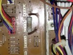
I'll reflow all the solder again tomorrow, hopefully it's just a joint. Cant actually make out the part number, the prints faded - put a pic below hopefully you can make it out. Maybe R3 or A3?

IMG_3584.JPG
 
I believe that is "R3". It wouldn't be "A3" because it's a resistor.

R=resistor
VR=variable resistor (like a pot or slider)
C=capacitor
D=diode
S=switch
Q=....quansistor...hahah...just kidding. "Q" stands for transistor. Why they didn't go with "T" I'll never know.
T=transformer...okay...that's why they used "Q" for transistor..."T" was already taken.
U=integrated circuit (a "chip"...like an opamp)
L=inductor...okay screw it I guess many of the letter designations don't match up with the component name.
TP=test point


I just looked at the schematics. R3 on the Mother (2) PCB is a voltage divider...it reduces the AC voltage to the meter lamps. So it has nothing to do with your transport problem. Since it is overheating you may need to or want to do more than just reflow the solder joints...remove the part and clean up the pads, and then scrape off the lacquer from some of the traces that lead to those pads so you can stuff the resistor back in further than it was...that way the tails will stick through more on the solder side and you can bend each tail so it lays on the traces past the pads...more contact area is what we are trying to create. It may not be a bad idea to replace the part even though it isn't the cause of your transport problem. It's a 2W 4.7ohm flameproof resistor.

Regarding the right tension arm dropping in PLAY, you need to stop fretting about all the problems that are happening. That's not meant to offend. If my theory is right and the reel motors are getting starved for electrons, they aren't going to keep up with the takeup and holdback tension in PLAY and the tape will go slack.

Your 388 is sick.

Don't expect it to do anything right.

You say it was working okay until you last worked on it? Tip it back up and inspect closely your work. Don't go shotgunning a bunch of stuff at once just shooting in the dark. If you find something suspicious, resolve it...just that one thing...then power it back up to see if it has an effect good or bad.

You reflowed all the solder joints on both the power supply and reel servo plugin cards as well as the solder joints for their respective motherboard pins?

Also, there will *always* be *some* heat coming from the right side of the cardbay. The power supply generates heat, all those transistors along the back of the heatsink generate heat (that's why there's a heatsink), etc.
 
Great advice there.
I always need someone to stop me and say relax...one thing at a time...be logical.

I'd want to be sure the resistor is overheating first. If you're just concerned that it's hot and that's it, consider that it might be totally normal!
If it's smoking or going red or definitely didn't get hot before, then fair enough. I'd sort that first.

You've reflowed solder joints and an overheating resistor has too much current flowing through, so a reasonable guess is you've accidentally bridged two points/traces allowing that to happen.

Find out which side is supply side and trace the other, looking for a mistake.

A friend of mine has to get irritated with me in order for me to listen to the "slow down" caution. It's the only reason I identify the prudence and offer it here, because I myself would be charging ahead like a greyhound on crack.

I am pretty sure that resistor is indeed getting too hot...based on the browning I see on the body of the part and the scorching of the component side of the board where the resistor tails go through...and there should not be much current going through that resistor...it is on a 7V AC rail that only powers the 10 meter lamps.

So something is not right. Hence the advice to tip it back up and take a careful a close look at things. The smallest problem can have big results. Get a good bright flashlight and if you have a magnifying glass use that too to look over the board carefully.
 
I don't work on these anymore and I guess you know the reason why. At Teac Chicago they had a metal frame made to attach to the unit and to be able to flip it over. If the R3 is getting real hot it is doing its job and will soon open. You take a DVM set to ohms and with the power off and go looking for the reason the load end of the resistor is getting so hot. It is because the current through it is excessive. Excessive current means too low a load on the load side- look for shorted leads, solder bridges or any reason the resistance is too low. When you find it and remove the problem the resistance will got back up.
The resistor looks to be 2 or 3 watt. Often time when people replace lamps in meters and get the wrong lamps they use automotive lamps that have a real low resistance. They draw a 1/4 amp. This is 5 times the amount the original lamps are suppose to be- Did you change meter lamps recently? If not look for pinched wires or whatever is the reason for a low load resistance. The resistor should not get hot if things are working correctly. This is a fuse resistor and is there to burn out if too much current is drawn.

The solder of the part on the foil pattern is NOT the reason it is getting hot. Regardless of the model these ideas still apply to electronics circuits in general.

So if you have 10 meter lamps at 55mA each that adds up to be .55A and using I^2R =P the power of the load is 1.42W so a 2 or 3 watt resistor should do the job. Using 1/4A lamps could add up to 2.5Amps and 29 Watts for the resistor to handle plus I thing that supply would collapse. It usually does and take the audio with it.
 
I am not an expert by any means but if I may make a suggestion, did the resistor have that dis-coloration when you first opened up the unit?? Sounds to me like it did... Can you measure the voltage drop across the resistor and then calculate the current flowing through it?? Then using ohm's law, calculate the power being dissapated and see if it exceeds the 2W power rating....if it does, something downstream is causing too much current to be drawn due to a partial short?? If the current draw is at something like 1.5 watts, then the resistor would have discolored over a period of time and if so, if you removed one leg it will probably measure the right value....and if that is the case, the temperature would probably be normal.........for what it is worth......I had to repair a Suzuki digital piano awhile back and I had a 10 ohm, 2W resistor that appeared to run too damm hot....the resistor was dis-colored and so was the area underneath it.....I did everything with it....checked out voltage regulators, ohmed out traces, etc, etc....finally, I re-installed the board and fired it up...that was about two years ago...the piano is still working fine.....so sometimes it is normal for this kind of thing...I would install a new resistor and mount it up away from the board as high as I could within reason......and then continue on with the other issue(s) that you have.......
 
Thanks for chiming in guys. Skywave, completely understand why you don't work on them, I've realised this week it weighs as much as a small car. Ridiculous. I did actually change the bulbs a few weeks ago, I've put a link to the ones I used below. They draw 100ma, do you think that's alright? I'm in the process of re-soldering everything, and I've order a replacement resistor. Have noticed a few things as I've been doing it though:

The row of transistors that's attached to the heat sink, one of the wires was literally hanging on by a thread. Also noticed that two of the plastic washers that stop them contacting had melted slightly. I'm going to test the continuity later, but I guess that's not a good sign? Also whoever had it before me had really gone at this board, the solder on the underside was pretty bad, so think some of the problems may be coming from that?

Also noticed down on the transport pcb that one of the M5L8243P's had a crack in the top. I've ordered a replacement, thinking that might have something to do with the rr ff problems??

All the boards are out at the mo, going to take me a few nights to reflow and check them all over. One of the channel boards was playing up on the eq, sure enough the ring on the solder side for the pot had lifted. I'll get all these board reflowed and looked over, then I'll report back later in the week.


lamps - | Axial Filament Indicator Lamp, Clear, 5/8 V, 100 mA, 5000h |
 
I think those lamps may be on the high side in terms of the amperage rating, but should be alright notwithstanding other possible issues.

Remember...

DON'T DO A BAJILLION THINGS AT ONCE!

Step by step. You'll end up chasing your tail

The transistors on the heatsink relate to the power supply. If a wire was damaged like that it would cause high resistance and high heat, melting the isolation washer and possibly causing additional voltage leakage. The parts need to be replaced along with the isolation washers. I'd get new insulators too.

Are you *sure* the soldering was jacked up by somebody and isn't factory? Can you post a pic?

Regarding the M5L8243P...if you want some input/answers, you HAVE to start offering some more detail. I've advised this earlier. Don't make your helpers have to pry for info.

When referring to a part be specific about the name of the board it is on...the name Teac gave it...if you don't know then take the time to post a pic so we can see. And we need the part identifier (like U101, R10, C28, etc.). You're asking specific questions about the M5L8243P part but then offering no specific information necessary to answer the question.

You think the 388 is heavy? Try moving an Ampex MM-1000...tips the scales at about 700lbs. :eek::D
 
Thanks for chiming in guys. Skywave, completely understand why you don't work on them, I've realised this week it weighs as much as a small car. Ridiculous. I did actually change the bulbs a few weeks ago, I've put a link to the ones I used below. They draw 100ma, do you think that's alright? I'm in the process of re-soldering everything, and I've order a replacement resistor. Have noticed a few things as I've been doing it though:


lamps - | Axial Filament Indicator Lamp, Clear, 5/8 V, 100 mA, 5000h |

Oh, didn't realise you'd changed the bulbs. That makes the approach much easier! Work out total current draw with old and new, and try putting the old bulbs back in.
If your new bulbs are simply drawing more current overall then there's the answer, but replacing the resistor without finding the cause isn't going to help.

At this stage I'd say either the bulbs draw too much or there's a short somewhere down-stream but, either way, I think I'd focus on sorting it before moving on.
 
From the datasheet, that chip appears to be some kind of bus multiplexor for a microcontroller. If it fails I would expect some of the deck functionality to be completely unresponsive, since it would stop the control logic from being able to access it. That at least is what the chip is designed to do - without seeing the schematic it's a bit of a guessing game, as Sweetbeats says.

I would definitely leave it alone for now. Unless it's on the motor control board itself, I can't see a way that chip could easily cause fast wind to slow down. AFAIK that kind of precision digital motor control is only found on high-end decks like late-model Studers. Either way, if you're at all unsure about your previous soldering work, I would not risk desoldering a chip as you're more likely to damage the thing further.
 
Back
Top