You are using an out of date browser. It may not display this or other websites correctly.
You should upgrade or use an alternative browser.
You should upgrade or use an alternative browser.
High “whistling” noise from my guitar/bass amplifiers in my home recording facility
- Thread starter Bad Disciple
- Start date
Bad Disciple
New member
Yeah... ok those "smart meters"... But if they're not giving a constant emission, it should not be my case. And I don't have one in my house.
So after having done all possible combinations for temporary solutions that I've described previously, I'm still in the fogs of nowhere. I also tested the "one-end-bond-shield-of-a-balanced-cable" as suggested by ecc83. The result is that it just diminished the "whistle" but it's still there, inacceptable for recording. So, I'm really frustrated as my work has completely stopped. I'm wondering, should I not use a guitar cable going in a DI box and a balanced-to-unbalanced cable from its output going in the amp?
Otherwise, I suppose the only thing left is to call a specialist with a professional field meter or whatever it's called, to measure all the wave ghosts that dance in my place. And I've been told they are expensive. And still not sure if a solution will be found... But I have no other choice.
Thank you all guys, for your valuable suggestions. I'll come back with any possible results to let you know.
Right, if the "Shielded Return" (as I have dubbed it) cable gave SOME improvement that shows I think that we are on the right lines and the problem is definitely a high RF field.
My next step would be the ferrites. Radshak? Do you still have a Tandys nearby (all gone here) ? The next step* would be the construction of an RF filter box that put RF "stoppers" in both the hot and shield wires. We used to make these up in 2oz "baccy" tins because they were Tin plated and you could easily solder and "hang" bits in them. Ally will do but you would have to install solder tags.
If you like I could draw something up for you? DI boxes? Yes could well help but a buffer VERY close to the guitar and then a 1:1 traff with an interwinding shield close to the input would I am sure stop the rot! This is all the more frustrating because I HAVE most of this RF/audio "junk" kicking around here and one day it will all be skipped!
*The very best way to stop RFI is inside the offending gear itself but that is not of course an option. I have modded lots of amps, radiograms and such over the years. I am at NN5 5** Google E me and then Rugby and Daventry, some BIG Mother transmitter there a couple of decades ago.
Dave.
Bad Disciple
New member
Hi Dave, and thanks for all your thoughts.
So, I'll try those ferrites and they have them in my local electronics' shop (I am in Belgium while you seem to live in the UK or AUS?). But before I go to buy them, I found few of them lumps on different old cables, hope they will do for testing. Do I have to make a loop with the cable or just one pass is enough (my cable is 7mm diameter, so it doesn't fit twice)?
Some of your other suggestions go too much tech-wise and overpass my electronic knowledge (remember I'm just a recording musician often forced to mess with electronics, but not more). So, I'd be very thankful if you send me some drawing about what you described.
Hi Dave, and thanks for all your thoughts.
So, I'll try those ferrites and they have them in my local electronics' shop (I am in Belgium while you seem to live in the UK or AUS?). But before I go to buy them, I found few of them lumps on different old cables, hope they will do for testing. Do I have to make a loop with the cable or just one pass is enough (my cable is 7mm diameter, so it doesn't fit twice)?
Some of your other suggestions go too much tech
I am in UK. For some reason I thought you were in USA? Belgium eh? Well that is not THAT far from my son in Normandy.
Yes, you want to get as many turns through the ferrite as you can, sometimes need a couple or even more but then it gets a bit silly and we try another tack.
Yes, I will get my pencil out this evening, an RF filter box is far from rocket science, if you can make cables I am sure you can follow a schematic with a layout?
Oil be bek. (Oh! Sorry, that's the Austrian one.)
Dave.
Bad Disciple
New member
Hi Dave, and thanks for all your thoughts.
So, I'll try those ferrites and they have them in my local electronics' shop (I am in Belgium while you seem to live in the UK or AUS?). But before I go to buy them, I found few of them lumps on different old cables, hope they will do for testing. Do I have to make a loop with the cable or just one pass is enough (my cable is 7mm diameter, so it doesn't fit twice)?
Some of your other suggestions go too much tech
I am in UK. For some reason I thought you were in USA? Belgium eh? Well that is not THAT far from my son in Normandy.
Yes, you want to get as many turns through the ferrite as you can, sometimes need a couple or even more but then it gets a bit silly and we try another tack.
Yes, I will get my pencil out this evening, an RF filter box is far from rocket science, if you can make cables I am sure you can follow a schematic with a layout?
Oil be bek. (Oh! Sorry, that's the Austrian one.)
Dave.
Ok, that's shining! So yes, if you send me a tech drawing, I hope I'll make it to put all pieces in harmony. But please, try to use some more popular slang than the tech one, to be understood by simple mortals. ;-)
I just tried with a cable and one of those lump pieces of ferrite I found on an old cable - but I only passed it through just once as it's too narrow for a loop - and it seems to get the same result of small attenuation. So, I wonder should I go to Brussels center 25km far to buy one of those special ferrites or not?...
Yeah, Normandy is 400-500km far from here, not much further than London for example... And by "AUS" I meant Australia. Myself I lived in the States for awhile in the past.
Cool vibes!
Ah! The tekky jargon! Not much we can do when you need to talk about tekky things. If you are bleeding you brakes you need to know what "Dot 4 " is! I have been doing forums for a good while now and my reply is always the same, Tell me the word or words that confuse and I will break it down for you. Every hobby/activity has its vocabulary, it is up to folks like me to help but ya GOTTA ask!
Dave.
Dave.
Bad Disciple
New member
Ah! The tekky jargon! Not much we can do when you need to talk about tekky things. If you are bleeding you brakes you need to know what "Dot 4 " is! I have been doing forums for a good while now and my reply is always the same, Tell me the word or words that confuse and I will break it down for you. Every hobby/activity has its vocabulary, it is up to folks like me to help but ya GOTTA ask!
Dave.
Please, don't even mind my joke. Of course, you should use your tech jargon and if anything is misty for me, I'll search on Internet or will just ask you back to break it down to small coins.
")
Bad Disciple
New member
Hi Dave,
Finally, I bought one piece of ferrite but again they didn't have a larger diameter, so it's just a 7.5mm and my cable cannot pass twice through it and the result is just the same as the previous tests, nothing better. Maybe if I find a larger diameter it might work better but, that's what it is now. So, my only hope is to make a filter like you suggested, or to call a local professional and... search... until finding the mystery. I'd really appreciate if you could send me that tech drawing when you can. Thanks a lot.
Finally, I bought one piece of ferrite but again they didn't have a larger diameter, so it's just a 7.5mm and my cable cannot pass twice through it and the result is just the same as the previous tests, nothing better. Maybe if I find a larger diameter it might work better but, that's what it is now. So, my only hope is to make a filter like you suggested, or to call a local professional and... search... until finding the mystery. I'd really appreciate if you could send me that tech drawing when you can. Thanks a lot.
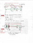
Please see attached schematic and wiring diagram.
The RF chokes, L1,L2 are one milli Henry types (1mH) and Maplin (.co.uk) prt # WH47B
The capacitors are ceramic 100 pico Farads (100pf ) again Maplin prt # RA36P But the value of each is not at all critical and you can source them from any electronics hobby shop.
The jacks must be plastic types and therefore insulated from the can. They are switched types and so the L&C junction points are "floating" once a plug is inserted. You could use non-switched jack but that would make the construction a little trickier.
The capacitors add an extra 50pf to the "load" on the guitar and so cause a tiny extra HF loss but this amounts to barely 1/2 mtr of guitar cable and I would very much doubt you would notice it. In any case use the shortest cable from output to amp input as this is not filtered.
I would expect the filter to have a dramatic effect on the RFI but if it is only partial you can increase the effect by putting another LC section after the capacitors.
Good luck and PLEASE come back with any and all questions, no matter how trivial they seem to you.
Dave.
Attachments
Bad Disciple
New member
Great, thanks Dave. I'll study it and will come back to you in the WE, as I'm busy with teaching whole day today. I'll possibly have few short questions. For example, I can't read well the note "metal box ... tin plate", should the metal box be tin covered or? Another thing I'm afraid is that whatever length of a cable goes to the amp, even a 1/2mtr, it immediately captures the "whistling" noise! So I imagine, should I not use an angled plug for the output from the box to plug it directly in the amp, instead of any cable?
I'll come back to you later, as I anyway have to wait till I get the parts posted, unless if I find them in the big electronic shop in the town.
I'll come back to you later, as I anyway have to wait till I get the parts posted, unless if I find them in the big electronic shop in the town.
Great, thanks Dave. I'll study it and will come back to you in the WE, as I'm busy with teaching whole day today. I'll possibly have few short questions. For example, I can't read well the note "metal box ... tin plate", should the metal box be tin covered or? Another thing I'm afraid is that whatever length of a cable goes to the amp, even a 1/2mtr, it immediately captures the "whistling" noise! So I imagine, should I not use an angled plug for the output from the box to plug it directly in the amp, instead of any cable?
I'll come back to you later, as I anyway have to wait till I get the parts posted, unless if I find them in the big electronic shop in the town.
The box can be anything to hand. "tinplate" is thin steel coated with Tin as per the baccy tins and most food tins (though many are Aluminium and plastic coated these days) The advantage of tinplate is that it solders very easily, ally does not. You COULD use an ABS box and line it with copper foil or butcher a bean can! .
The OP lead problem? Make a VERY short one? You can buy plug to plug jack "couplers" but would need some tracking down. Make the OP cable of the "shielded return" form I mentioned before.
I am becoming more and more convinced that this problem will only be truly resolved by an internal mod to the amp etc. That LC filter could just as easily be incorporated INSIDE an amp. In fact I know a guitar amp Co (cough!) that do just that!
Dave.
Bad Disciple
New member
The box can be anything to hand. "tinplate" is thin steel coated with Tin as per the baccy tins and most food tins (though many are Aluminium and plastic coated these days) The advantage of tinplate is that it solders very easily, ally does not. You COULD use an ABS box and line it with copper foil or butcher a bean can! .
Dave.
Hi Dave, just a quick question: Could that box be also made of aluminium? Cause I don't find Tin-plated ones, just aluminium.
(I bought the Ls, the Cs and the plastic switched plugs in the Electric store in town. Later I'll have few more questions for you).
Hi Dave, just a quick question: Could that box be also made of aluminium? Cause I don't find Tin
Yes, Ally is fine but it cannot be soldered to by standard kit so you will have to either drill a hole for an M3 n&b plus a solder tag or find a large solder tagged washer for the output jack and use that as an earth point...Or you can just put a bare wire loop around the jack thread.
Here ALL the time!
Dave.
Bad Disciple
New member
What's the best metal for that box? Can I make it from a steel sheet? Or from a mesh?
What's the best metal for that box? Can I make it from a steel sheet? Or from a mesh?
Ha! Well the very BEST material for RF enclosures is Silver plated Copper! No need to go that far though. Any common metal will do.
Dave.
Bad Disciple
New member
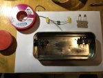
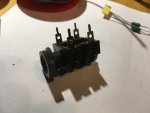
Ok, so my good lady found me a metal box something from her mother, which seems just right. I already tested it for soldering and yes, after using some acid paste it bonds! I also bought the materials from that shop in town. I showed them the values you suggested. Here I send you pictures of the items.
I also have two questions that I wrote on your drawing which I colored to make it fanatically clear for myself and you'll see it on the attachment.
I hope this will finally put an end to my peripeteia which has stopped me from work here and a second week.
Tomorrow I'll give you a report.
I also have two questions that I wrote on your drawing which I colored to make it fanatically clear for myself and you'll see it on the attachment.
I hope this will finally put an end to my peripeteia which has stopped me from work here and a second week.
Tomorrow I'll give you a report.
Attachments
Bad Disciple
New member
Hi Dave,
I'm almost done with putting together the RF filter. Suddenly - by seeing the reference of chokes I bought - I realize that the guy in the shop gave me chokes of 1UH (!) [referred as inductors, right?] while I see they must be 1mH. Is that the same or I must undo everything and go buy the correct ones?
I'm almost done with putting together the RF filter. Suddenly - by seeing the reference of chokes I bought - I realize that the guy in the shop gave me chokes of 1UH (!) [referred as inductors, right?] while I see they must be 1mH. Is that the same or I must undo everything and go buy the correct ones?
Don't stop at this point. 1 micro H will indeed have much less effect but will have some, as will the capacitors so press on and finish the filter.
If you find it has little or no effect, get the 1mH chokes and just chop one end of the existing ones and put them in series. I guess we are not talking a lot of money here?
Dave.
If you find it has little or no effect, get the 1mH chokes and just chop one end of the existing ones and put them in series. I guess we are not talking a lot of money here?
Dave.