Ampex MM-1000 Story...

Yep! I hear you on all that!

Arduous project eh! :D

Anyway, good luck on the rest of it and have to say again how impressed I am with all the progress you've made so far on it! Your skills and patience to do all this is exemplary! :cool:

Cheers! :)
 
Am I correct in my assumption that the EECO box didn't provide for one transport's controls to control the other? IOW if you needed to FFWD to a spot further along in the project you had to manually hit FFWD on both machines and use the footage counters to get both transports close to the pre-roll point, hit PLAY on both and then let the sync box do its thing and lock them up? It wasn't a sophisticated system as you would have on a set of full servo transports right (where the sync box can assume full control over all transport functions of the slave machine)?

That's about right. Those were the days when each session had two engineers, and the guy running machines might have just as much experience as the guy running the console. We were already adept at logging the times from the counter relative to the song structure. When the producer said "let's punch in the second line of the third chorus" we could get the tape where we wanted it fairly easily. With a little more work we could get both machines parked very close to the same spot on the tape. Then once they started up, the synchronizer would get them together. The closer we had parked the two tapes, the faster they'd sync. Although we didn't always run both machines during overdub sessions. Often we'd print a rough mix on two tracks of the slave machine, and then just run the slave during the tedious overdubbing. Of course then they would both be synced up for the mix.

I don't miss all that extra bother. But I sure remember the sound of those machines fondly. You've got a good one there. I'm sure you're going to enjoy it.

BTW I don't mean to sound like I've given up on tape. Quite the opposite. If you'd like to see what happens when someone just can't keep pretending that digital sounds good, check out the website of one of my companies:
www.tapeproject.com

The narrative account of the sync'ing process is priceless...thanks for that. I have a sync cable schematic for my Micro Lynx and an MM-1200. I believe there is a close relationship in those servo systems so there's hope to slave the MM-1000. That would be sweet, and I don't mind having to manually shuttle the transport to the pre-roll point. Having the capability to slave the MM-1000 would open the door to being able to slave to MTC coming off my DAW. By using timecode offset points and storing them in memory on the Micro Lynx I could track 7 tracks at a time and then dump to the DAW and then move to a different point on the tape and key in the offset and track another 7 tracks, dump, offset, track etc. In this way I'd never have to track over my original analog tracks but I'd be able to build a large multitrack project all tracked to the MM-1000 and all the DAW tracks would be direct native tracks from the MM-1000. I'm not thinking I'd often need to/want to build some guhugic project, but I'd be able to and still run the more economical 1" tape as long as any one session of the project didn't call for more than 7 tracks at a time. My mixer features only 12 channel strips, but there again would be a hybrid realtionship between the DAW and the analog mixer: sum and group less critical tracks in the DAW while using the analog mixer to sum the more critical tracks.

Also, quite familiar with the Tape Project. I appreciate what it is doing for the analog tape medium. ;)

Thanks so much again for contributing to the thread!

Daniel and Jeff, thanks for the comments!

It is looking nice...certainly much better than when it arrived, but I still keep comparing things to the M-520, 48 and 58 that used to be part of the herd...they were minty. The MM-1000 has plenty of nicks and scratches...it toook me a long time to get the 39V power supplies cleaned up...they both had a layer of sticky stubborn oily grime on the top. It was nasty. I felt like I was cleaning an engine block...but then again the MM-1000 is more like a truck or a tractor, and part of me is settling in well with all the blemishes. I suppose it is the same thing as when somebody likes the look of a "distressed" instrument...there's a story in those nicks, scuffs and scratches...actually some parts of the MM-1000 with their scuffs and such remind me of how equipment was "distressed" for the Star Wars series of movies...they made things look old and many of those things were industrial looking devices...and so it is with Matilda.

Jeff I'll try and use your suggestions with taking pictures in the future (from over in the "Wallpaper" thread). Thanks again for "having fun" with some of the pictures. Truly is amazing what you churn out. ;)
 
Okay all you analog dogs...

Got the headblock in. So-so pics below and some other updates.

IMG_6026_3_1.JPG


IMG_6028_5_1.JPG


IMG_6029_6_1.JPG


I mentioned earlier about the nylon washers that bush the lifter bases from the deck plate being shot...years ago I made a bunch of mylar strips out of old drum heads when I used to make drums...the strips worked great for the straps needed to connect snare wires to the throwoff on a snare drum. Still have a bunch around and these actually work great as a glide surface under the lifter bases. I trimmed a couple to length, and it just happens that my wife has an 1/8" punch in her card making tools which is the same size as the posts of the lifter bases that go into the deck plate...punched holes and put a couple spots of tacky strip on the ends of each mylar strip to hold them in place. You can see the strips ready for the lifters in the first pic, and then the lifters in place and linked up to the solenoid in the second one.

IMG_6016_1_1.JPG


IMG_6017_2_1.JPG


You know your machine has heavy-duty casters when there are grease zerks to lube the axles...I didn't take a pic of them but there are also zerks for the turnstiles of the pivoting casters...:eek:

IMG_6031_8_1.JPG


I removed the takeup reel motor so I can use it to turn and trim the new cork material to make new reel table corks. I'm a bit disturbed as there were a whole bunch of shim washers that fell out when I had to tip the motor assembly to get it out. I'm assuming the are likely for reel table height (since the reel tables are fixed onto the massive motor shafts with a hefty roll pin and 4 set screws...:eek:) so I may have some work to do after getting things put back together but I'll cross that bridge when I get to it. First off, here are the fasteners that hold the motor assembly to the deck plate...these are some of the highest quality stainless steel socket head cap screws I have ever seen...

IMG_6030_7_1.JPG


I leave you with a shot of the motor assembly sitting in front of the manual binder so you can see the scale of the motor assembly...it was surprisingly light considering its size...15lbs maybe? Merry Christmas everybody!

IMG_6033_9_1.JPG
 
Indeed! Many parts of that beast bare more resemblance to a tank more so then to a sound recording device! :)

Thanks for the additional pics! Always fascinating to study the detail and craftsmanship that went into making it! :cool:

That last motor assembly shot might make for an interesting glamor redo too! ...maybe! :D

Cheers! :)
 
New reel corks

Reel cork replacement is well under way. Dave Dintenfass of Fulltrack Productions sent me some rough-shaped sheets of the fabric-backed cork material for a very reasonable sum and even included an extra to cover the inevitable screw-up...not only is he nice, but wise too. :D

I did get three good reel corks out of those sheets, and one is installed on the takeup motor. I must say its a bit of a tedious process, but the alternative is nothing...nowhere that I know of anymore that has these and the old ones were really, truly shot.

Here is the motor assembly with the reel clamper removed and the table cleaned. You can see the old cork there leaning against the bottom of the motor assembly. I was happy to find that there is a recessed area for the clamper on the table which eased concerns about keeping things centered.

IMG_6055_1_1.JPG


Here is the cork material. You can see the fabric backing, and the combined material is the proper thickness...

IMG_6056_2_1.JPG


So I laid some washers in the recess so the cork material wouldn't buckle when I temporarily sandwiched the cork in between the table and the clamper...then I took a plain piece of paper and, laying it on the reel table, rubbed the paper to get an impression of the position of the table center and the three clamper mounting holes. Then I could cut out those impressions and have a template for marking rough positions of those holes on a piece of the cork, then sandwich it, then spin the table and just hold a fresh razor blade against the clamper body and, bingo was his name-o I had a cork donut with a nice donut hole and a rough outside. Then it was just a matter of removing the clamper to get the cork "sandwich meat" out, remove the washers, properly reinstall the reel clamper, lay the donut on the table, clamp a reel on there to hold the cork and then spin the table again this time using the edge of the reel table as a guide and the back reel flange as a stop for the razor blade. Enter new MM-1000 reel cork. The first one I spun the reel motor using a hand drill, but I found I could just do it by hand and get just as good a result without the drama.

Here's the beginning of the paper template (you can see the reel table with the temporary spacer washers in the clamper recess...)

IMG_6057_3_1.JPG


Here is the cork sheet to be shaped, holes transferred from the template and cut...

IMG_6058_4_1.JPG


Here's the result of the first cut...you can see the table there in the background with the cork "sandwich meat" still in between the clamper and the table...

IMG_6059_5_1.JPG


Finished cork ready for gluing (with contact cement):

IMG_6065_9_1.JPG


Reel motor reinstalled...this was a knuckle-biter with those shim washers mentioned in my last post...It turned out there were four 0.010" washers and four 0.015" washers, and one 0.002" washer. I measured the deck plate as well as the motor mounting plate as best I could with my dial calipers and everything was within 0.001"...there was one corner of the motor plate that was 0.001" less so I put the 0.002" washer there. I used grease to try and hold them together on the motor plate and that didn't work, so I ended up holding the cap screws in place with masking tape so the washers had posts to keep from sliding off...it worked.

IMG_6066_10_1.JPG


IMG_6067_11_1.JPG
 
Lots of other notables...

In the front-right corner of the transport face are two holes clearly (and not too carefully) drilled for something...turns out there used to be a splicing block mounted there and guess what? I'm thinkin' it was the same as the one I have because it screwed right on...cool...you can see the holes in the first picture in post #85. Here it is now (also you can refer to this pic in the last post...):

IMG_6062_6_1.JPG


Got the new cooling fan wired up and mounted...noisier than I thought or hoped for...might be better with the 39V power supplies right over it...if not I'll need to figure out how to step it down in RPM...

IMG_6063_7_1.JPG


Couple shots of the back of the console coming back together...both 39V supplies are remounted (bottom left), 24V supply is ready to go (just above 39V supplies, and the Control Relay Box is the upper-most unit on the left...now properly mounted on hinge brackets so you can tip the Control Box out to easily get to the tension resistors. I'll test the supplies again with the oscilloscope before powering the system up just to be sure (after all my cleaning and dickering)...

IMG_6069_12_1.JPG


IMG_6070_13_1.JPG


The viscous reel idler flywheel all cleaned up...

IMG_6072_14_1.JPG


And here is that 2U blank panel I straightened out along with the power cable and remote jack panel...I painted this too...doesn't quite match but close enough...good for a rattle-can...see sort of a before shot here (definitely qualifies as banged-up on my book...you can see the 'S'-bend by looking at the light reflections on it), and then here is an (unfortunately non-descript) after shot:

IMG_6064_8_1.JPG


There is a long list of other minor things that have been done over the past couple days including repairing one of the lower side panels...getting closer...
 
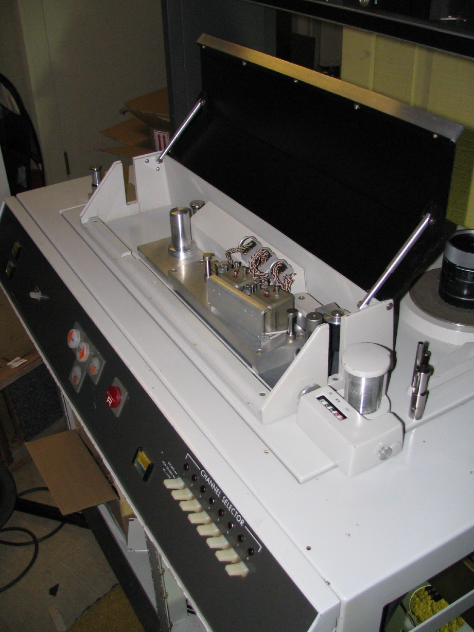
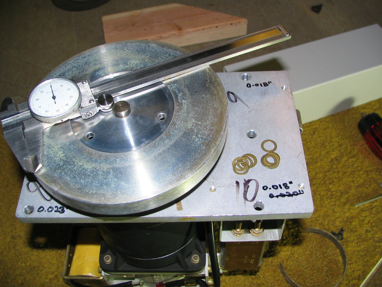
I got everything reinstalled that had to come out in order to get the takeup motor out for the reel cork replacement procedure. This is a bit of a chore just because I have to work upside-down. On a "normal" sized deck I could turn it the way I want in order to gain best access, but of course Matilda sits how she wants and I have to reorient my body...reminiscent of working behind the dash on my wife's VW Rabbit, laying upside-down in the driver's seat with my head down by the pedals. Anyway...

So I got all that stuff back in and I've removed everything in order to gain easy egress for the supply motor. Perfect example of sweetbeats' OCD. See, I 
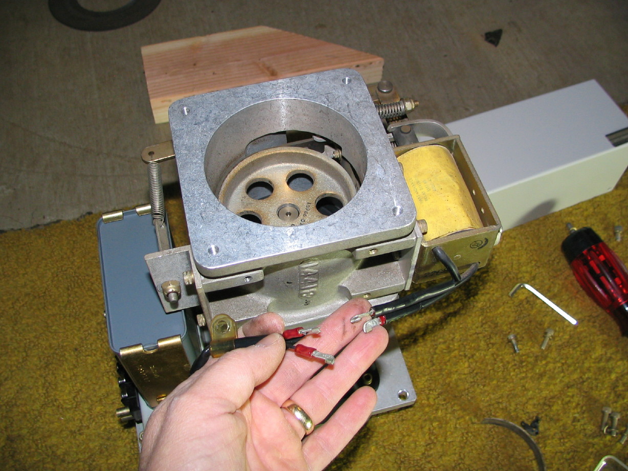
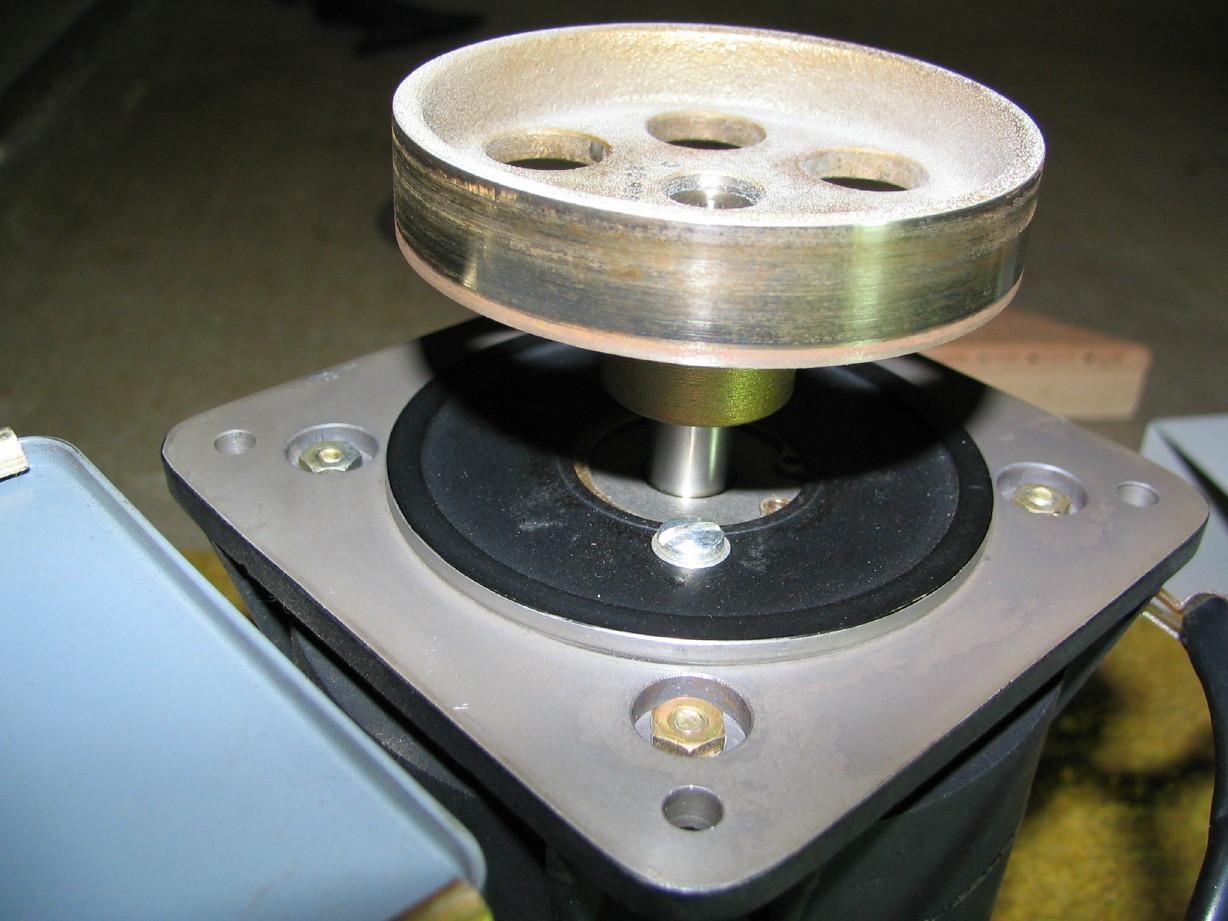
could just leave the motor in, pull the old cork off and clean it up with acetone, put the new cork on and be done with it but when I pulled the reel clamper off the takeup table there was a small pile of aluminum shavings in there. I have a feeling there may have been mechanical failure at some point causing a reel to keep spinning on the table and there is a spring-loaded tab on the reel clamper core that could scrape on one of the adapter donuts used when running the machine as a 1". Anyway, I just can't stand the thought that there might be aluminum flakes inside the supply clamper assembly and you can't get to the bolts that hold the clamper on unless you remove the motor. Plus the bolts that held the clamper to the takeup table weren't all that tight and I'd feel better getting the supply-side properly torqued. ANYway (yet again...)...

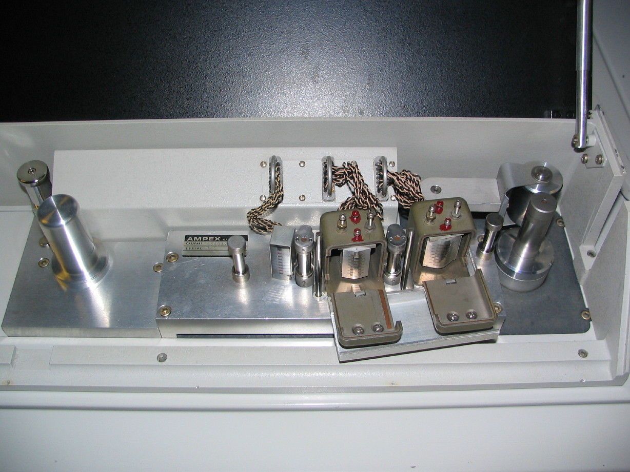
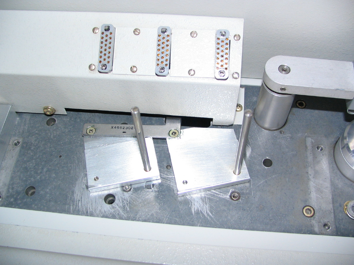
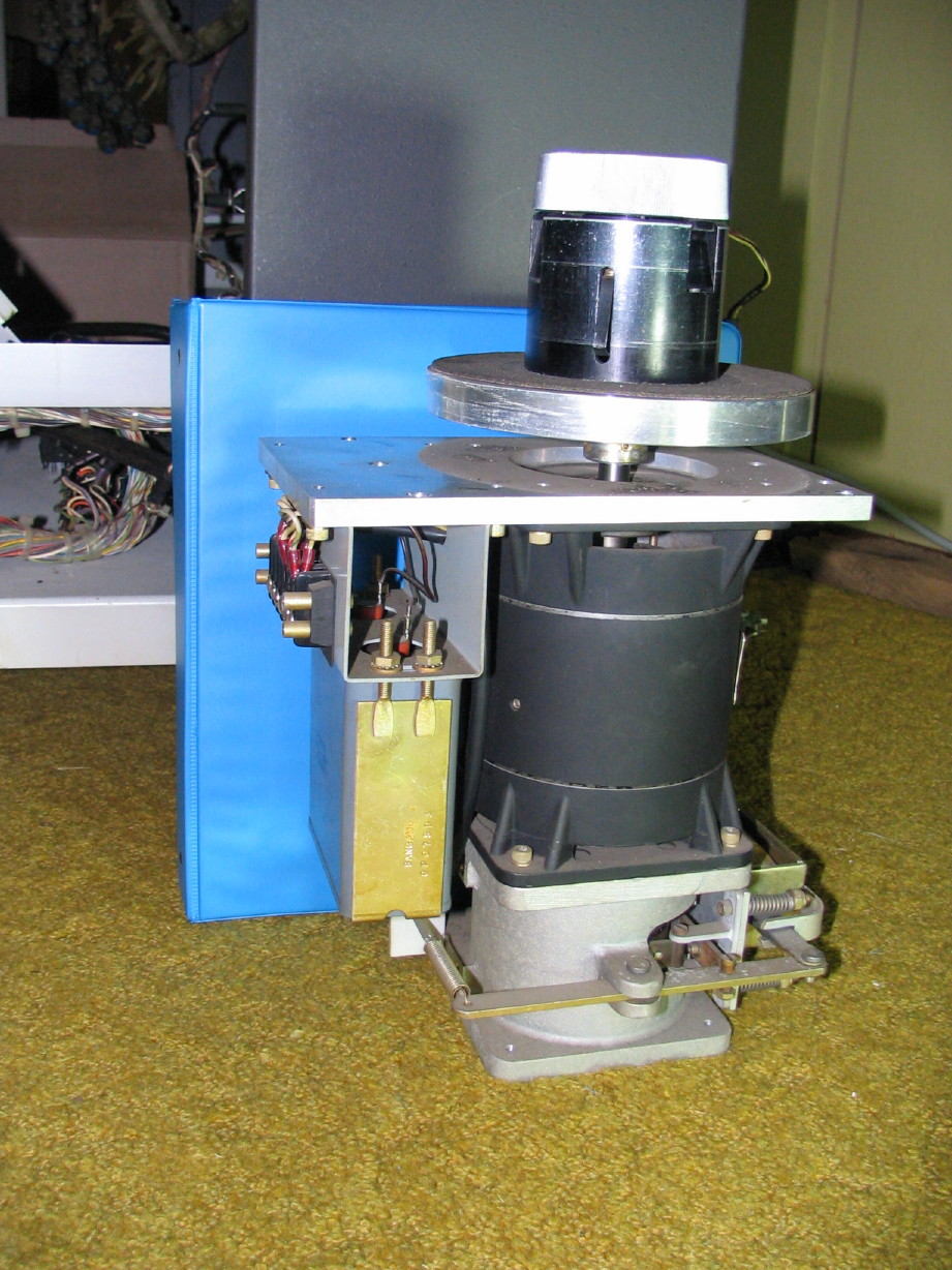
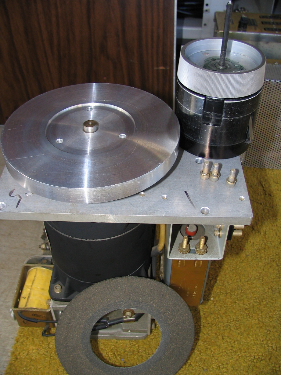
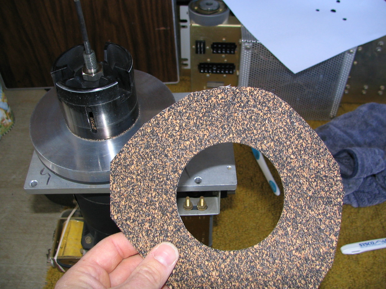
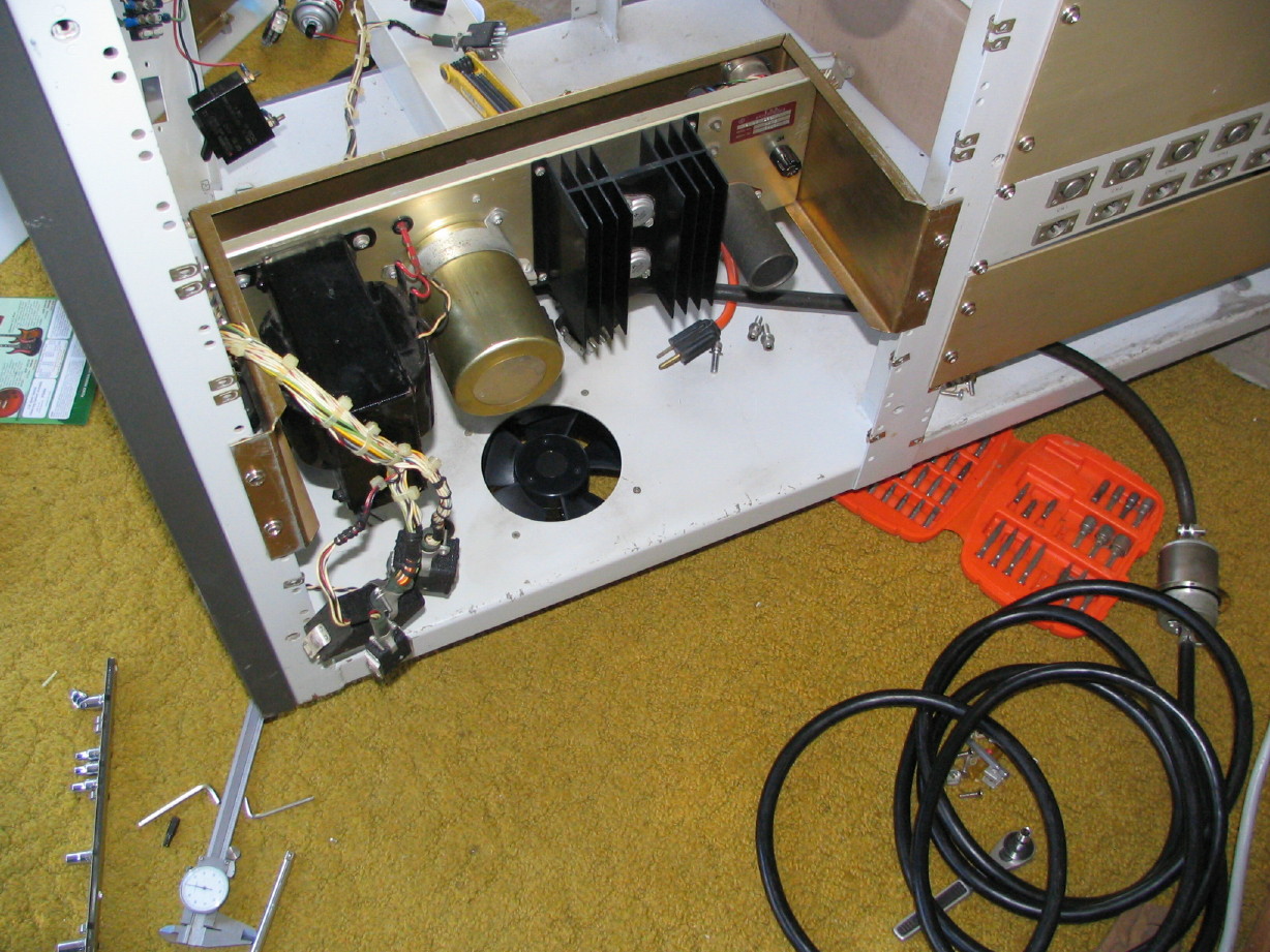
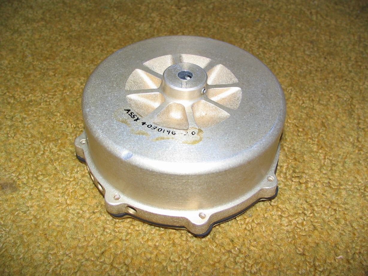
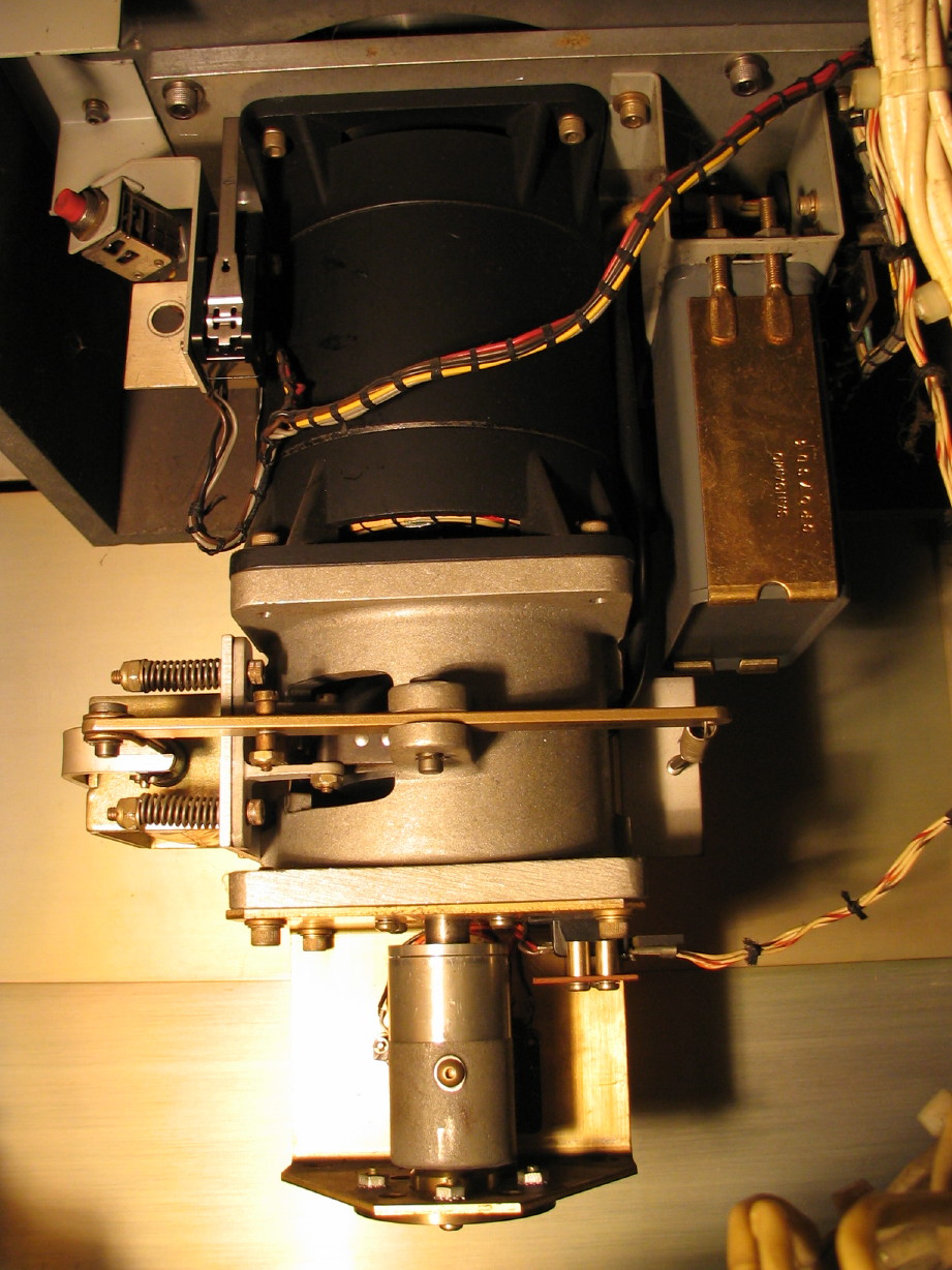
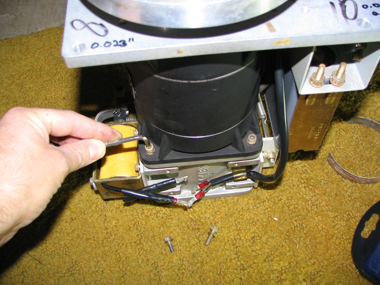
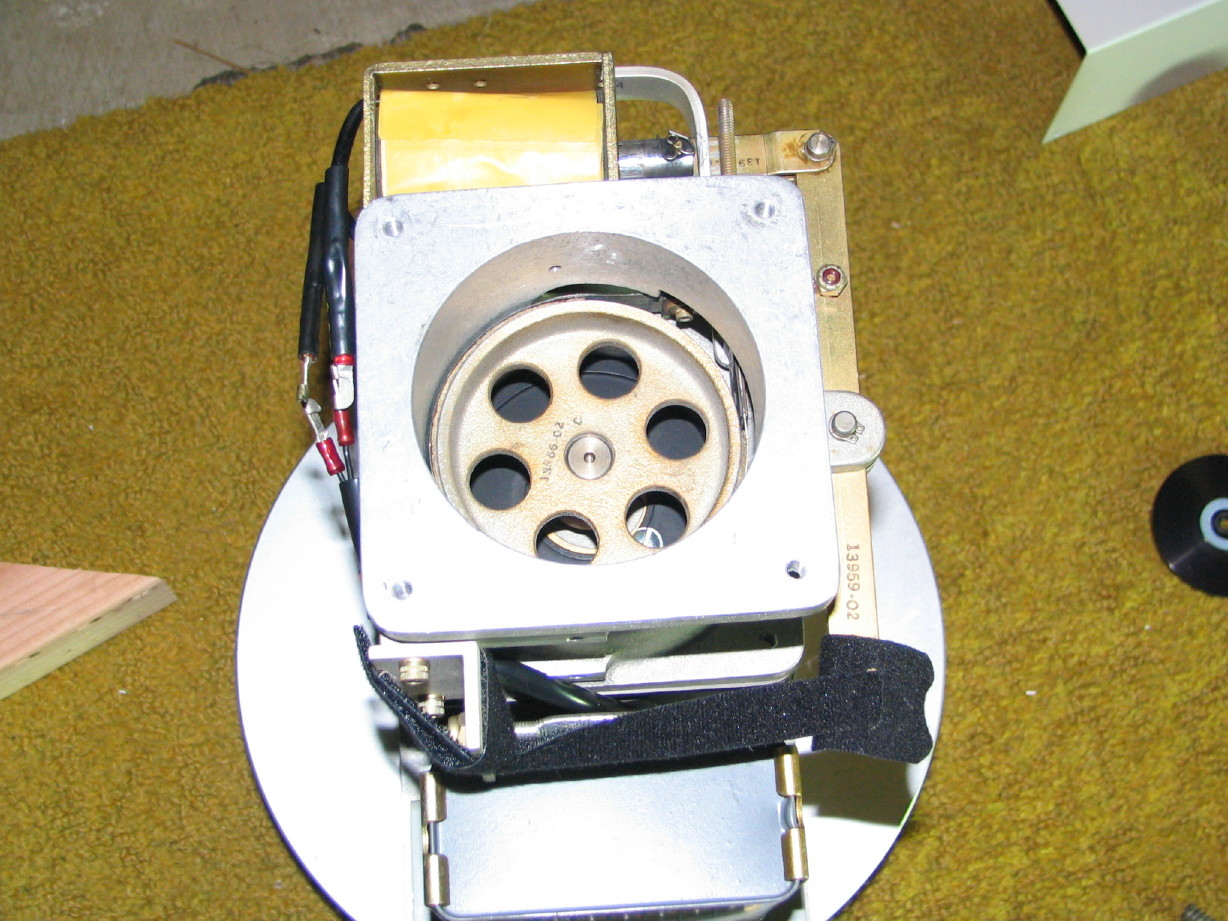
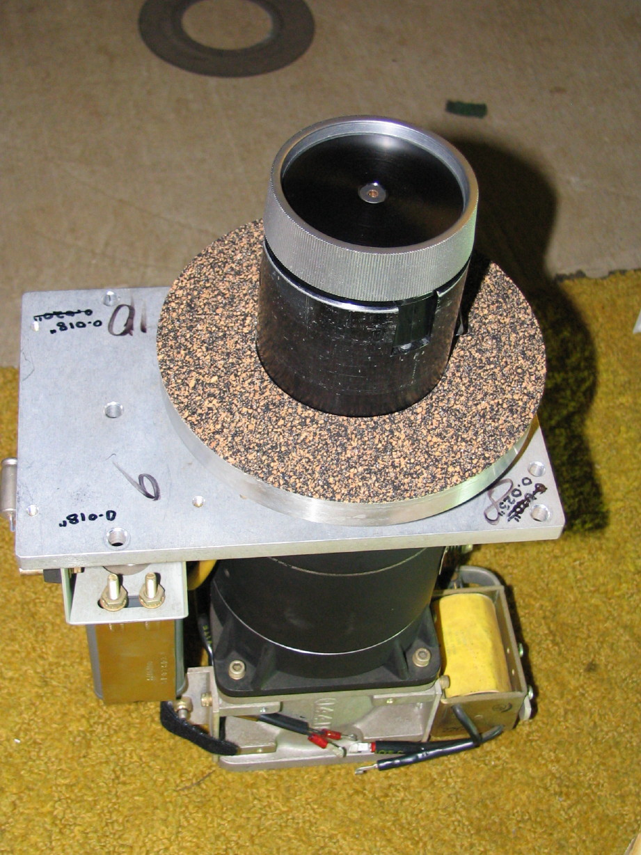
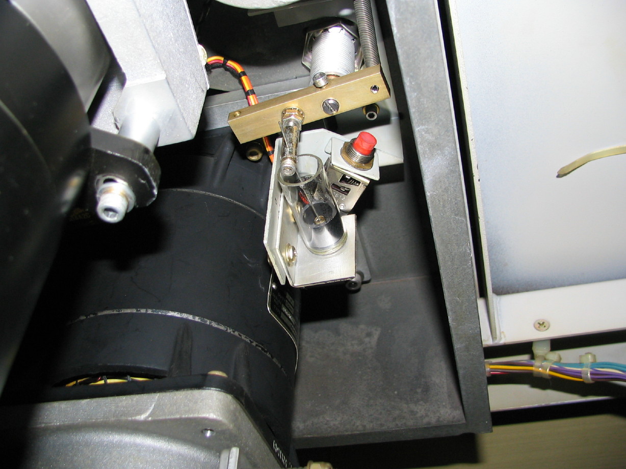
I just need to remove the 4 bolts that hold the supply motor assembly to the deck plate and drop it down. One of the items that I removed was the motion sensor assembly...Its the smaller cylindrical assembly at the bottom of the motor assembly stack:

IMG_5657_3_1.JPG


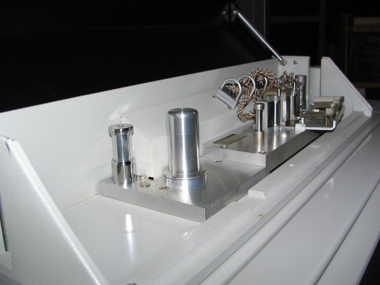
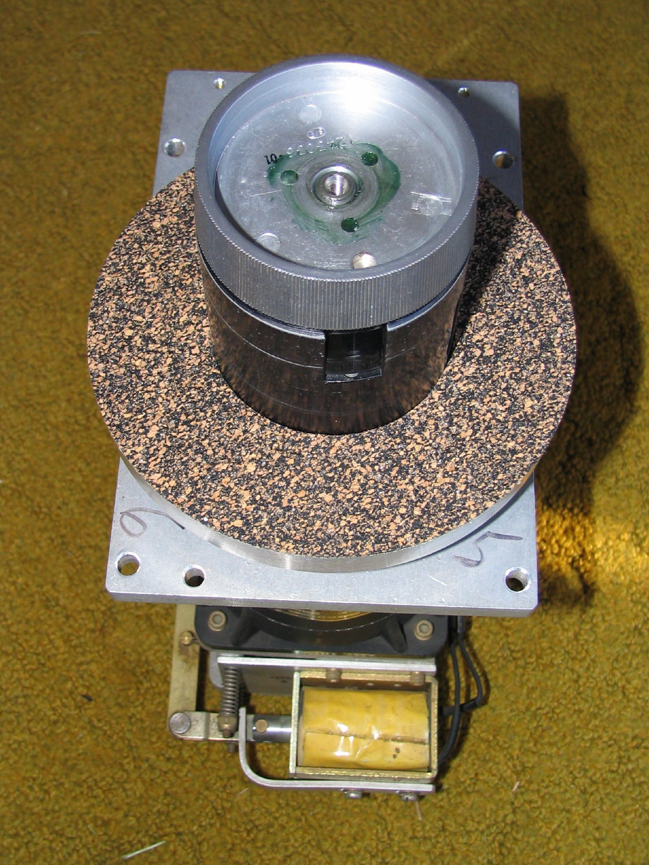
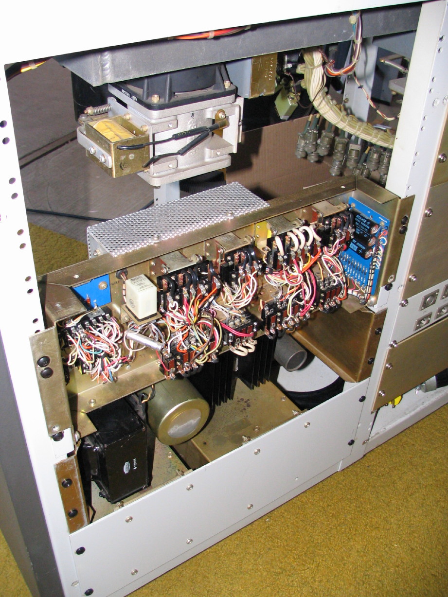
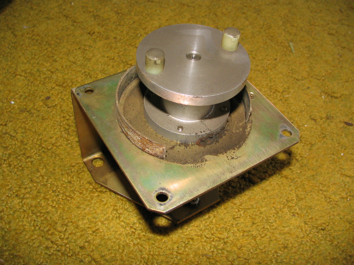
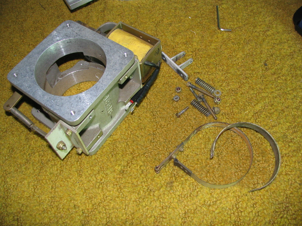
I pulled it just to shorten the stack up...make it easier to manipulate out of the console and also, with it removed, the stack sits very nicely on the brake housing. Well, remember that the supply motor is the one where I can't figure out why the brake isn't working, but I know it is a mechanical issue...I now know what the issue is...check this out...when I dropped the motion sensor assembly down the brake pad was sitting on top of the sensor bracket:

IMG_6074_2_1.JPG


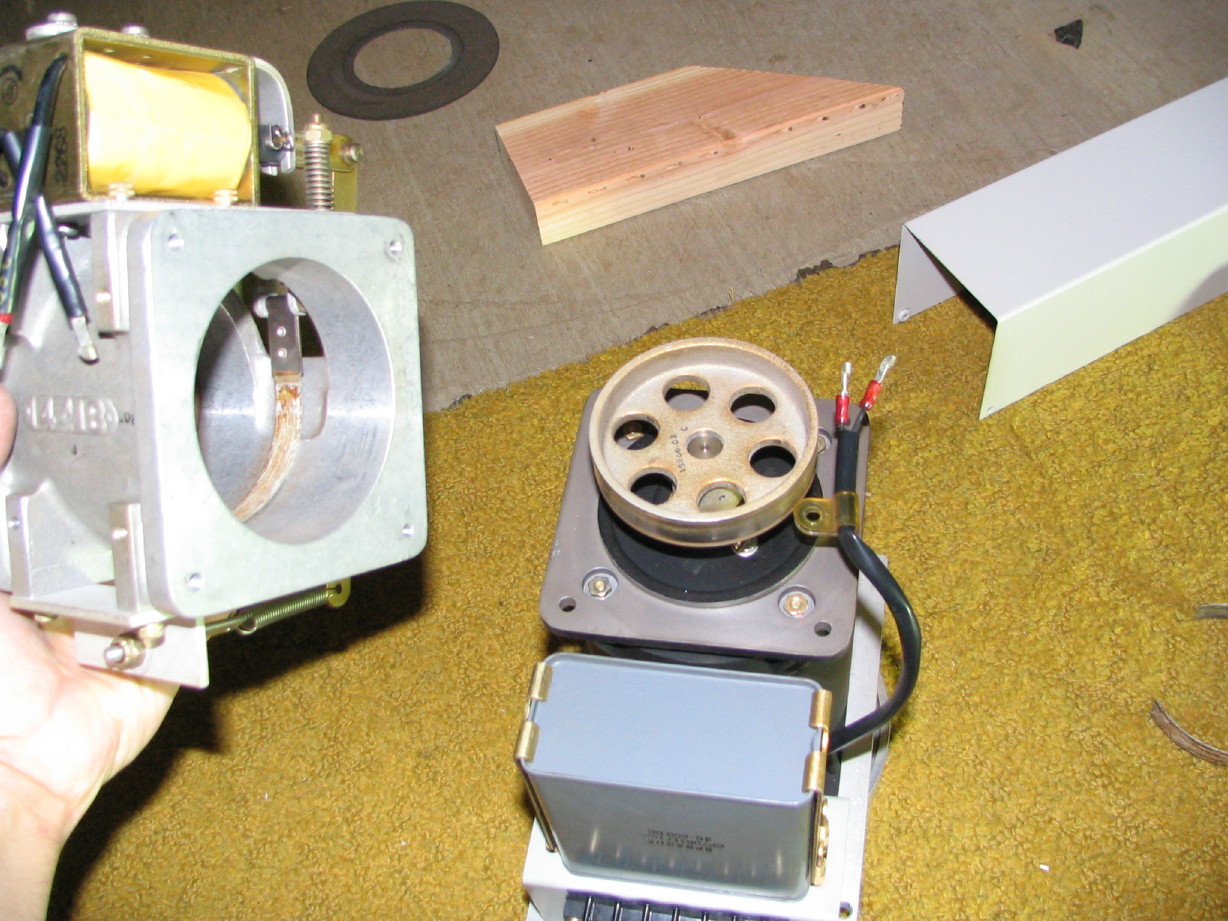
See, this is the stuff I love to discover. I bet that brake has been non-functional for years and nobody could figure out why or cared, but it is such a simple fix. I believe I can just remove the brake band, clean everything up really good and use contact cement to re-adhere the pad to the band...problem solved. I'm sure having that brake non-functional has wreaked havoc on the operation of the machine.

The 
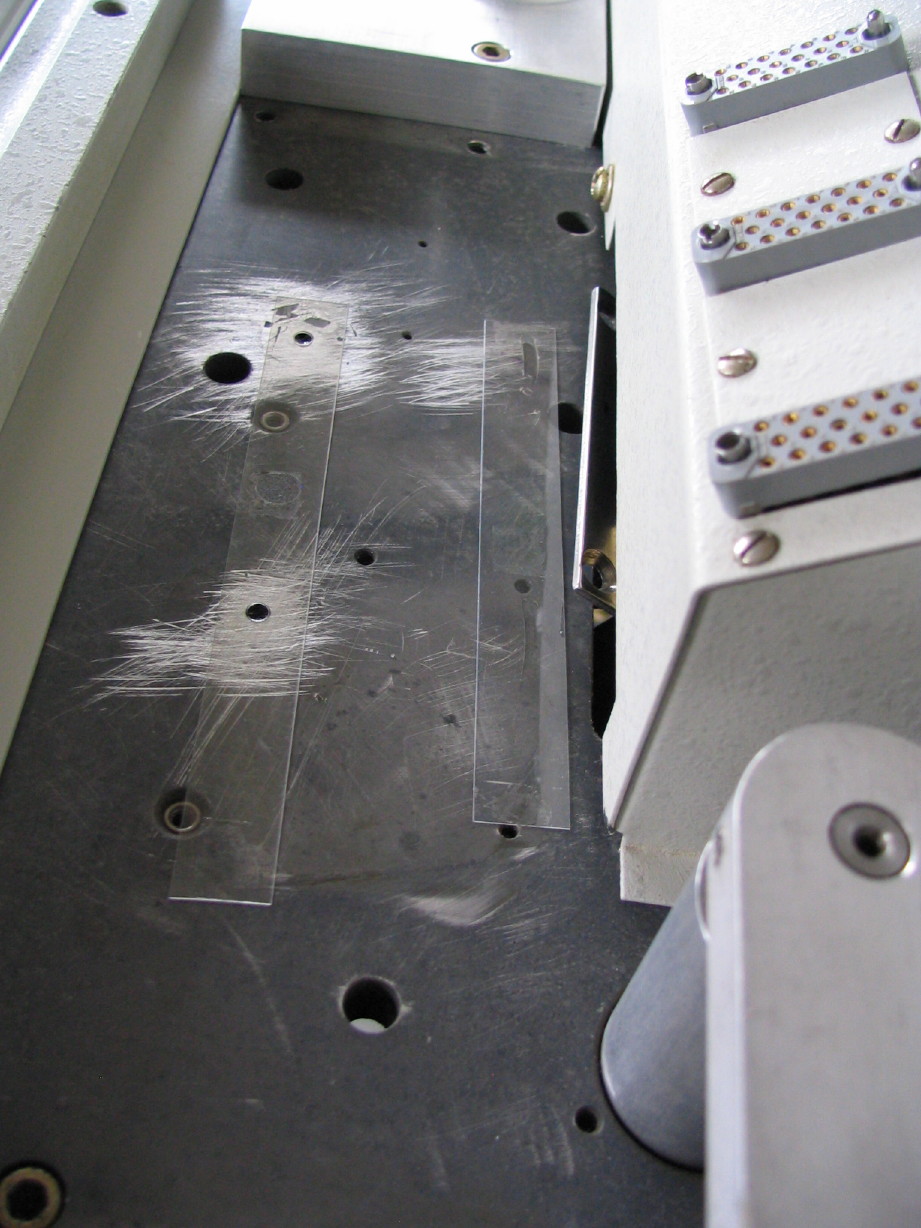
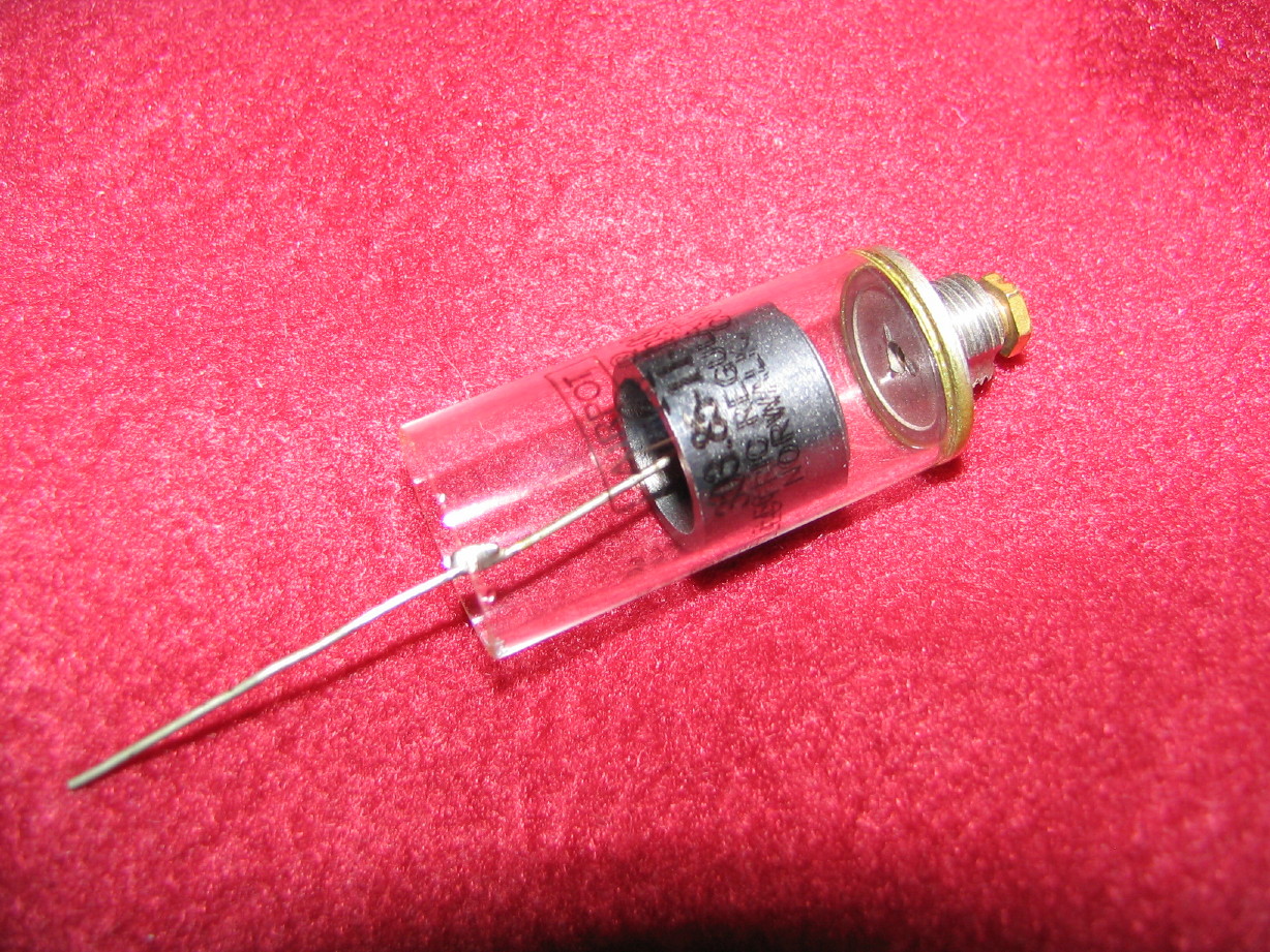
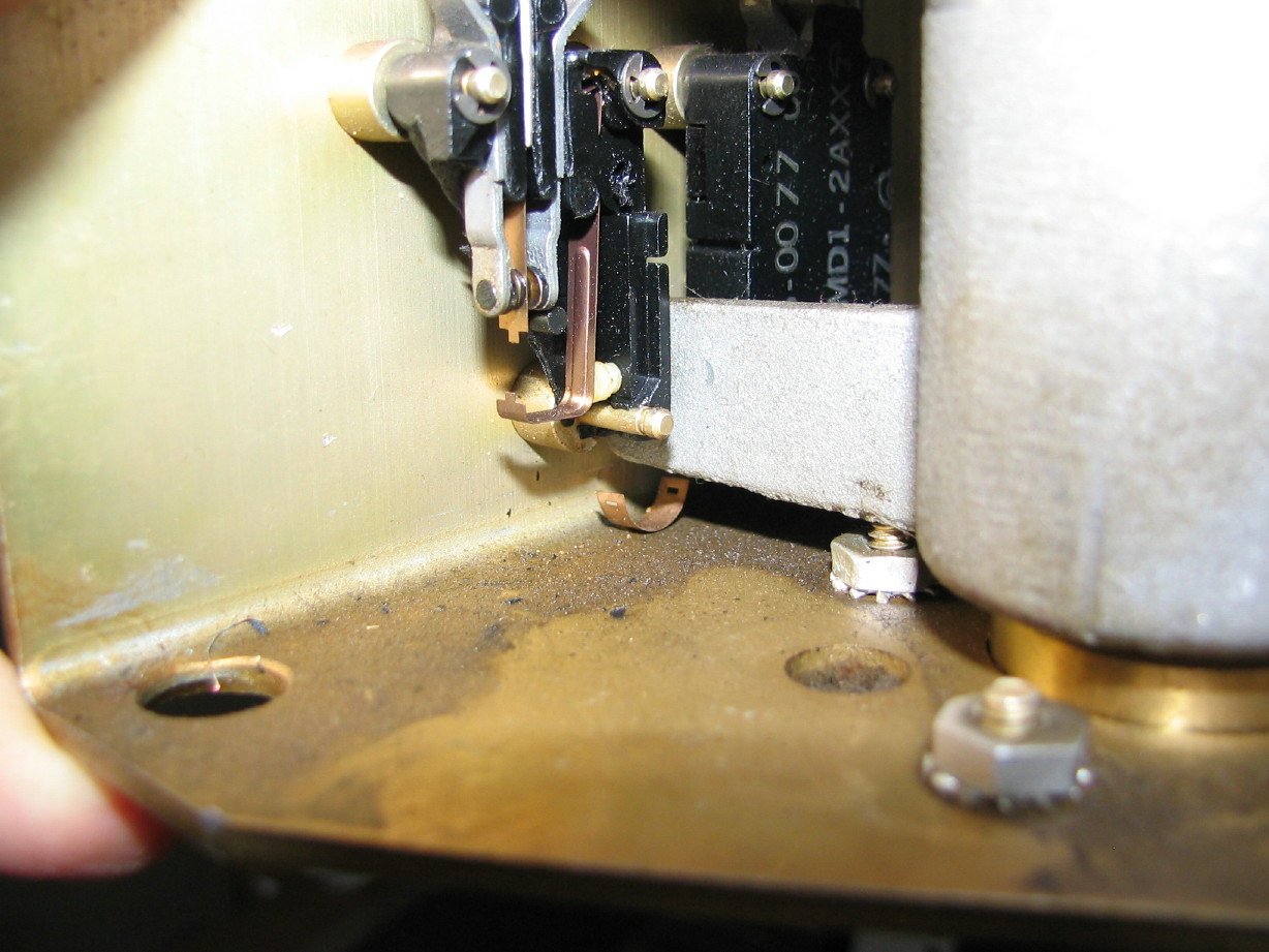
other thing I discovered when I pulled the motion sensor assembly is that the micro-switch that wasn't actuating (you may recall...the one that I could see wasn't working and then noticed that part of it seemed missing and then I saw, much to my relief, the little metal 'U'-shaped piece that completes the micro-switch linkage perched on the sensor bracket under the switch) is not only missing part of its linkage but (duh) now that I can see both switches at varying angles I see the switch with the impaired linkage is actually *busted*...missing, like, half its shell. It would probably still work but I gotta find a replacement. If the switch threw its linkage at the wrong time it could cause tape to snap so...here's hoping. It appears to be a standard part and actually I'm sure there are a number of switches that will work but I hope to find a direct replacement. Here's a closeup shot of the broken switch...you can see its healthy twin to its right...makes you wonder what happened...:

IMG_6075_3_1.JPG


Now, I just have to say, that the whole motion sensor assembly is the most aggregious example of over-engineering I have yet to find, which is kind of scary because the machine is dripping with over-engineering, but watch this short YouTube video and maybe you'll understand why I feel that way:

YouTube

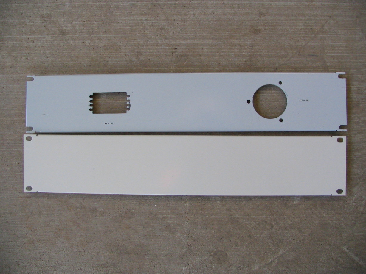
Last but not least I am in the midst of cleaning up the "breaker panel"...that's the power switch, but it is an actual 15A single-pole breaker mounted on a 2U rack panel that mounts on the lower right of the console. There are +120VAC and COM buss bars mounted behind the panel too. Just taking that all apart, getting all the dust and scunge off of it and cleaning all the contacts good.

So, next up, I'll drop the supply motor down, clean up the reel table, put the new cork on, fix the brake band and try to find a replacement switch for the motion sensor.
 
Last edited:
Supply Reel Motor Repairs Underway

I had a productive couple hours last evening working on Matilda.

Got the supply reel motor out to replace the reel cork, conduct a general inspection/cleaning and repair the brake band.

I've learned my lesson and for all of you out there with MM-1000's, if you remove a reel motor beware of the shim washers perched on top of the motor plate. When I took the takeup motor out I wanted to save the headache of taking the stuff off around the motor and then having to reinstall which then required a jockeying the motor to get it out around the stuff I didn't want to remove...that's what led to the shim washers raining all over the place. This time I just went ahead and took that other stuff of (the bracket that holds the dashpot, tension arm spring and brake release switch) so the motor could be dropped straight down. Then I took an inventory of the shim washers and labeled the motor plate with the total shim thickness to be reinstalled when motor goes back in:

IMG_6191_3_1.JPG


Then it was time to remove the brake assembly.

First I disconnected the wires to the brake solenoid and removed the screw holding the wire assembly to the brake housing. Ampex used "scissor" type connectors...slide back the insulator and unclip the connector using a scissor motion.

IMG_6188_1_1.JPG


Then you remove the 4 cap screws that fasten the brake housing to the motor housing.

IMG_6190_2_1.JPG


And, after compressing the solenoid plunger to fully release the brake band, off it comes! You can see the old cement on the bare metal brake band.

IMG_6192_4_1.JPG


A little closer look at the bottom of the motor housing and brake drum. Look at the lip on the bottom of the motor housing...that's the mating joint between the two housings and it is a very precise fit...BTW, I had done no cleaning on the motor in this pic...pretty good for 40 years huh?

IMG_6194_6_1.JPG


Within a few minutes I got the brake band disassembled and out of the brake housing. Then it was a matter of cleaning up as much of the old adhesive as I could from the band and the pad.

IMG_6193_5_1.JPG


Here is the reassembled brake assembly back on the motor. You can see the band and pad back together in there. I used standard contact cement. I put a velcro strap on the end of the actuator lever to keep the band and pad squeezed against the drum and I'll leave it that way for a few days to give it a good chance of holding for good and to keep it closely formed to the drum as it sets.

IMG_6196_7_1.JPG


And here is the new reel cork installed. There was, as I suspected, a small pile of aluminum shavings inside the reel clamper housing. All clean now.

IMG_6197_8_1.JPG


I also got a bunch more cleaning done on the floor and front face of the console, as well as a bunch of the wiring and the main power throw switch...also got polish on the throw switch panel...sheesh...who else makes a reel-to-reel recorder with a heavy-duty 2U panel just for the power switch?? Overboard? Yes. Cool? I don't know...don't care. Me likey.

SO...I'm going to get the neutral and hot buss connections cleaned up that go next to the main power switch, buff the power switch panel, and once that goes back in along with the supply motor then its time to test out the transport functions again. I didn't want to do that until the supply brake was fixed, but I think that should all be good now...everything else is basically ready to go. We'll see if all my work on the control relay box fixed the lifter issue and the capstan shutoff issue.
 
Supply motor is back in...not all hooked up, but at least its back into the transport...breaker panel cleaned up, reassembled and back in the console...
 
Just think.....

All this work just to move particles of rust around. :eek:

I guess that's the extreme pessimist side talking. But you're right about the over-engineering side of things. That's the understatement of the century.
 
Yeah...I know what you mean.

I've thought about that before.

What amazes me is that anything on Earth could make particles of "rust" sound so good y'know?

Its amazing. Its so low-tech and yet is such an interdependent amalgam of systems, some of which get prety stinkin' techy...but it is all still to move tape around and reorient oxide.

Why aren't we all asking (as we look at a tape machine) "you mean that stores sound [or video or data...take your pick]??? How does that store anything???"
 
Bit by bit...

I figure if I do at least a little bit nearly every day it will get 'there'.

I've actually done quite a bit over the last couple weeks.

Console is all cleaned up. It was a funny feeling when I put a foot on the face of the transport, grabbed the overbridge and hopped up onto it, standing on the transport in order to clean up the top of the overbridge. Why get a stool or step-ladder when I could just climb onto the machine itself like a jungle gym? I then had a fleeting vision of trying to stand on any other open reel machine I've had...not that there is any reason to need to do that but I was trying to picture where I would plant my feet on the BR-20T for instance...plenty of standing room on the MM-1000. So the console is all cleaned up except for needing a quick wipe-down on the underside and 3 of the casters still need 40 years of dusty scunge wiped off of them but that's low priority right now.

Getting all the pots and knobs put back together on the electronics after cleaning them...

Pulled electronics module #1 out, opened it up to straighten the card housing...all the cards were leaning to the left like 3 back-slashes. Purely cosmetic but it was really bugging me and it only took 5 minutes or so to rectify...

Got answers to questions I had about which cards belong in the MM-1000 since there is a little mixing and matching going on in mine. As I figured, pretty much everything that is installed will work, but I have enough spares to set it up so the card revision numbers match up and I'd rather have the signal path consistent. It will make troubleshooting a little less hairy as well though the differences in the cards are very subtle. Thanks to Steve Puntolillo for helping me with this.

Steve also took the time to answer questions about setting the scrape flutter idlers as well as how to set the tensions on the MM with a Tentelometer. I'll put more detail up on those as I get to them but the scrape flutter idlers aren't fixed and sliding them into position will upset the wrap and I just needed to know which comes first and it is just a back and forth procedure...back the flutter idlers off, set the wrap, slide the idlers into place to kiss the tape, recheck the wrap, adjust, check the idlers and back and forth one more time if necessary. And on the tape tensions, the manual only describes how to set the tensions using spring guages hooked to the reel tables. I'll put up a detailed procedure when I get to setting tensions but Steve shared how he sets the tensions on his MM-1000 using a Tentelometer.

Also cleaned up the rest of the cabling in the console...not spotless but just taking a window-cleaner moistened terry towel and working to get surface scunge off of the harnesses.

The latest challenge is to get the dashpot linkages reinstalled. Yeah...what ARE those anyway? Well, they are these neat machined brass bars that affix to the underside of the tension arm pivot shafts to which the tension arm springs attach as well as the dashpot piston. The dashpots are just a small glass cylinder inside of which is a piston. The movement of the piston is restricted or dampened because the movement of air inside the cylinder is restricted from getting in or out of the cylinder as the piston moves. The piston is linked to the dashpot lever so as the tension arm swings the piston is moved and therefore the movement of the tension arm is damped. IOW without a dashpot, if you swing a tension arm to its full extension (i.e. spring fully extended) and let it go it would snap back to th neutral stop. With the dashpot it slowly glides back to neutral. I think the purpose here is when the transport mode is changed the dampened tension arms help to distribute the load change on the tape, and I suppose they may help to smooth physical oscillations or 'dancing' or 'hopping' during fast-winding. The dashpot links also trigger the brake release switches (i.e. when you swing the supply tension arm to its full stop the supply brake is released, and same for the takeup arm and brake), and there is a safety switch on the supply side that is opened when the arm is in the neutral position as well. The safety switch energizes the transport when closed. So those links do quite a bit. The manual has NO detail about how to position them/adjust them but through messing with them I can understand how they should be set on the tension arm pivot shafts. I start by swinging the tension arm to full stop (full extension) and then, while holding the tension arm in place I rotate the dashpot link until it triggers the brake release switch but so there is still travel left in the switch plunger. I don't want the tension arm to be shoving on a release switch that has run out of travel before the tension arm has reached the stop on the face of the transport. So when I find that spot that's where the link gets tightened to the pivot shaft. On the supply side there is an additional adjustment screw on the dashpot link to open the safety switch and once the position of the link on the shaft is set with reference to the brake release switch then the safety switch trigger screw can be adjusted so it opens the safety switch when the tension arm is in the neutral position, but again, not to the point that the safety switch actuator has run out travel. Make sense? The tension arm stops on the face of the transport can do their jobs preventing the switches from taking a beating. I can tell you for certain these adjustments were not right when I got the machine now that I can logically process how things should be. On top of that the safety switch trigger screw was missing. PLUS the links were upside down so the return spring pegs were pointing down instead of up which would cause the springs to be angled and rubbing on the links. So those are back on BUT...something is wrong with my one dashpot. As an aside this was all a real PITA because all this stuff is tucked up into the transport plate recess (up inside the upside-down box) and its hard to get your fingers around stuff...anyway, the takeup tension arm never gets to neutral position and moves realllllllly slllllllow...like the spring isn't strong enough. AHA! dialogued with Steve Puntolillo again and he says the dashpots have an adjustable vent on them so I'll have a look at that. So, yeah...none of this stuff is in the manual. Looking forward to watching tape zip off the supply reel in fast wind and then seeing the tension arms glide to neutral...its the little things, okay?

Need to find another dashpot...

Once I get this tension arm stuff squared away I can remount stuff in the lower console racks (that has been left out to make access easier) and THEN it will be time to rescope and (if necessary) adjust the power supply outputs and then take it for a spin and see where things are at function-wise.
 
XXXXXXXXXXXXXXXXXXXXXX(*&$(*%&(*$&%(*$&%*( *(%(*#$&%(*$RGFGLKDSJLKJH$(*#$*TFGLFDH(RT LJH(T (*#$*($T((*(*XXXXXXXXXXXXXXXXXXXXXXXX )(*$()*T)#($*T)(*T) LFKGLKLDLFKJGKLJREOIGOIGUOIUF..................................................................... Make sense? .................


:laughings:

Trust me, if I was there looking at it, it would make perfect sense. I'm a bit too tired to understand this right now.

But BASICALLY it sounds kinds like those old pneumatic door closers, that if the vent is too tight, the door opens but takes like a year to close, right?
 
:D:D:D:D:D:D

Yah...that's the idea.

Here is a shot of the dashpot:

IMG_6227_2_1.JPG


Here it is mounted in the machine. You can see the piston "rod" (wire) is attached to that barrel nut on the "dashpot linkage", the brass bar. You can also see the return spring and the red brake release switch:

IMG_6228_1_1.JPG


I was able to remove the dashpot last night, disassemble and clean it and the adjuster works. Here is a YouTube video of the tension arm in proper working action:

YouTube

Just need to clean up the motion sensor assembly and see if I can get the one busted switch to work, at least temporarily, and then reinstall that. Then I can rackmount the noise reduction units and the sync gain/relay box and get on with it.
 
Last edited:
Just need to clean up the motion sensor assembly and see if I can get the one busted switch to work, at least temporarily, and then reinstall that. Then I can rackmount the noise reduction units and the sync gain/relay box and get on with it.

Looking at the pics of the switch, it seems like the plastic shell around the busted switch used to have a little white bumper thing that pressed up against the center contact flapper, right? Thus.....why the switch required the plastic shell, and won't work without it?

It probably broke from pure old age, I imagine. It's one of very few pieces of plastic in the transport, it seems.
 
Muck, are you talking about the busted motion sensor switch detailed back in post #89? If so, I really think the switch took a hit or was overtightened or something because the action on those switches is so light from the paddle that actuates them, and they are really solid units. I found a replacement though that I should have on-hand in the next couple weeks, and I *think* I may be able to get the current one to work in the meantime. I may clean up the motion sensor assembly tonight and dicker with and test the switch. That will be one step closer...
 
stupid lifters still don't work

Oh well...

I side-stepped my plan and tried out the transport last night. I knew I hadn't messed with the 24V supply at all and since the transport runs off that supply and it scoped nice before so I just disconnected the 39V supplies to see if all the transport functions were working right.

I was able to get the busted motion sensor switch functioning. Its a temporary fix as it is fragile and I don't like the contacts being exposed, but it works. Its kind of cool because the paddle that actuates the two switches (one switch to sense forward motion, the other to sense reverse motion) gets pushed back to the neutral position by the switch actuators. A neat self-aligning mechanical system for sensing bi-directional motion, and the STOP lamp only comes on when the tape has stopped...its not an indicator of what you are telling the transport to do, but rather a feedback indicator of what the transport is actually doing (lamp off if tape is still moving, lamp on when tape has stopped).

The lifters still don't work. I don't know if it is a bad solenoid, but I'm starting at the supply connections for the solenoid and working my way back because the supply contact of the solenoid is providing +4~5VDC regardless of the transport mode which isn't right. Out come the schematics.

The capstan shaft also still turns regardless of whether or not power is bypassed to the transport (i.e. when the left tension arm is parked it opens a switch that is supposed to de-energize a relay that powers the rest of the works), but the capstan keeps on spinning (albeit at 7.5ips regardless of whether you have 7.5 or 15ips selected as the system speed). That will take some figuring. I'm still getting comfortable reading the Ampex schematics; the nomenclature for connections from schematic to schematic.

This is just a noisy, noisy machine. If you like sophisticated refined transports that are smooth, efficient and operate with precision, this is not the machine for you. Clearly attention was not paid to the size and weight of the thing. Remember, off-the-shelf parts/assemblies were used by Ampex to get a 16-track deck to market quickly. The went to the shelves full of the absolutely absurdly overbuilt components available...all field tested bulletproof components and systems, but the size and power of this thing is just insanity.

Think of a pocket-rocket car...something that has been refined and tweaked...it has a great hp/liter ratio, runs clean and is relatively fuel efficient...the car is light and you couple that with a snappy high rpm motor that has been tweaked and finessed to produce a stupid amount of power on regular gas and it does what it does well, and handles well, and has good comfortable driveability...no special skills needed to drive it...it is gentle on tape, can function well in a sync relationship, maybe its a more narrow format machine but has the latest in head design techology and produces surprising performance. You get the analogy? Write your 8-track machine of choice in here __________ but I'm picturing a number of late-model Tascam machines because I know them better than other brands.

Now for the MM-1000...I'm thinking dragster...maybe even top fuel dragster. It goes in one direction, really fast. The engine is an overbuilt beast of a motor designed to produce ultra-stupid power that is focused in a pretty narrow rpm band. You have to put special fuel in it or it won't run and at that it barely holds idle. When you look at the structural and mechanical technology and engineering it is flat-out impressive...sure to draw a "wow" from anybody that appreciates such things. It does what it does extremely well but far a car it certainly isn't quiet, cornering is no real attribute, not comfortable, no family trips are going to work in it...won't function in a sync relationship, requires ideally two helpers to move it anywhere and for goodness sake watch your toes...it puts out a lot of heat and noise and isn't exactly gentle on the tape, but boy does it get down the strip fast and in a way that nothing else can.

Here is another YouTube video for your entertainment with tape loaded on for the first time.

Enjoy.

YouTube
 
Last edited:
Back
Top