You are using an out of date browser. It may not display this or other websites correctly.
You should upgrade or use an alternative browser.
You should upgrade or use an alternative browser.
Tascam M-___ Story...
- Thread starter sweetbeats
- Start date
sweetbeats
Reel deep thoughts...
I've only been following this sporadically...so then, does this mean you're able to power it up...some...and now just sorting out the different modules?
Were you able to make any use of the PS...with whatever mods you were going to do to it?
Oh I’m able to power it up completely and have been able to for years, but the Control Module wasn’t 100%, and there may still be some minimal issues to sort out with some of the I/O modules, one I know of for sure (with module #12). I’m still using the modified PS-520 supply, but I *absolutely* will be using the PS-3500 you gave me. That’s the “power supply upgrade” I mentioned in my post before the last. The PS-520 doesn’t have enough supply headroom in the main transformer windings for the +/-15V supply for all the active devices in the M-__, since it has quite a bit more of them than the M-520, and the PS-520 chassis lacks the physical space I need inside for the separate 2A 70V transformer and regulated supply PCB assembly to address the need for a regulated bipolar 35V supply with some oomph for the high headroom line out amps in the console. The PS-3500 addresses both of these issues, and, as of late last week I finally have all the parts on-hand for recapping and modifying the PS-3500, including the 28-pin Hirose Sumicon parts to modify my power supply umbilical to interface the M-__ with the PS-3500.
sweetbeats
Reel deep thoughts...
Stereo main outs and meters are now calibrated. I calibrated them to -10dBV at 1kHz. When the master fader was at unity the R channel was pretty spot-on at 314mV, but the L channel was at about 285mV, and the meters were a bit off. L-R outputs are now at 316mV +/-0.2mV at 1kHz with the master fader at unity, and the meters now show 0VU under these conditions.
I also checked how the oscillator is doing as far as accuracy at 1kHz...meter shows 1001.7Hz. Not bad.
[EDIT]
Oh and DC offset at the main out jacks is dead 0V.
I also checked how the oscillator is doing as far as accuracy at 1kHz...meter shows 1001.7Hz. Not bad.
[EDIT]
Oh and DC offset at the main out jacks is dead 0V.
Last edited:
sweetbeats
Reel deep thoughts...
Oh...I see.
I wasn't asking to check if you're using the 3500 PS.....just trying to get a quick sense of where you are at with things.
Oh yeah no worries...

Stereo main outs and meters are now calibrated. I calibrated them to -10dBV at 1kHz. When the master fader was at unity the R channel was pretty spot-on at 314mV, but the L channel was at about 285mV, and the meters were a bit off. L-R outputs are now at 316mV +/-0.2mV at 1kHz with the master fader at unity, and the meters now show 0VU under these conditions.
I also checked how the oscillator is doing as far as accuracy at 1kHz...meter shows 1001.7Hz. Not bad.
[EDIT]
Oh and DC offset at the main out jacks is dead 0V.
I dare say this old fool has missed something along the way but why set the Main Outs to 0VU for -10dBV and not the more usual +4dBu? And do you know the mixer's internal operating level? The optimum seems to be -2dBu (615mV) but this can vary depending upon the exact application.
Dave.
sweetbeats
Reel deep thoughts...
Internal operating level is -10dBV. I was calibrating using the unbalanced stereo outputs because my meter is unbalanced...just a matter of convenience. There are also balanced outputs for the L-R main buss and these are +4dBu nominal, switchable to +8dBu. I haven’t tested it but I expect they are outputting their respective nominal level when the meters display 0VU, but I figured, on top of the convenience issue above, it made sense to calibrate using the unbalanced outputs since these are the most direct outputs for the stereo buss and match the console’s internal operating level.
sweetbeats
Reel deep thoughts...
So with the Control Module 100%, I’m turning my attention to the testing and mods on the I/O modules. I’m creating a punch-list of tasks associated with each PCB of the I/O module, like a check-list of parts to replace or upgrade, modifications to execute, things to check, etc.
The EQ PCB is an impediment because there are certain things that can be done there to improve the signal path whether the EQ is switched in or bypassed, but the values of the parts and where to put the parts is somewhat unknown...some expert advice is needed. I have willing parties, but first a schematic is needed. I’ve tried to reverse engineer the EQ board. I’m sure I could do it eventually, it’s just a challenge even though it is similar to the PE-40 EQ, and I have the schematic for that. So...it’s just a mental block thing. I’m getting better at reverse engineering input and output amps, mic amps...but the EQ is taking more attention and since I only have small blocks of time peppered here and there it makes it harder to make headway...I have to sort of reorient every time I sit down with the board in front of me. I thought, “geez I wonder if I offered up some compensation if I could find somebody to reverse engineer it for me.” So I did that, and an acquaintance took the bait. This feels like a weight off my shoulders because I’d rather get back to heating up the iron and working through the modules, than breaking my brain stretching my abilities reverse engineering what is, to me, a complex circuit. So I’m sending off the EQ PCB from module #9.
You know that feeling just before you jump into a cold pool? You count to three and choose not to think and just jump? That’s how I feel boxing up part of the M-__ and entrusting it to the postal service. But I’m excited to be able to finish the punch-list and continue the project.
Internal operating level is -10dBV. I was calibrating using the unbalanced stereo outputs because my meter is unbalanced...just a matter of convenience. There are also balanced outputs for the L-R main buss and these are +4dBu nominal, switchable to +8dBu. I haven’t tested it but I expect they are outputting their respective nominal level when the meters display 0VU, but I figured, on top of the convenience issue above, it made sense to calibrate using the unbalanced outputs since these are the most direct outputs for the stereo buss and match the console’s internal operating level.
Neg ten is very low. I suspect the mixer was originally intended for broadcast use? For that you need the highest possible headroom but noise levels need only be better than FM or tape.
Can I respectfully suggest you build a unity gain balanced input stage around an NE5534 for the test meter?
I find all this most interesting and I hope my interjections are not TOO impudent!
Rock on,
Dave.
sweetbeats
Reel deep thoughts...
Neg ten is very low. I suspect the mixer was originally intended for broadcast use? For that you need the highest possible headroom but noise levels need only be better than FM or tape.
Can I respectfully suggest you build a unity gain balanced input stage around an NE5534 for the test meter?
I find all this most interesting and I hope my interjections are not TOO impudent!
Rock on,
Dave.
The interjections are just fine, Dave...I like the input.
The M-__ is no different than any of the other period Tascam gear in terms of unbalanced I/O and -10dBV nominal operating level; M-50/M-512/M-520/PE-40, etc. so it’s just as “very low” as most the stuff we like to talk about here. Who knows WHAT market it was originally intended to target, but it’s a bit of a Swiss Army knife, which isn’t inappropriate for a concept or prototype model...it’s pretty well suited for 8-track recording and small format FOH (simultaneously), and has broadcast overtones, for instance, yes, some of the outputs are +8dBu capable, and the underpinnings are there for a total of fourteen +8dBu balanced outputs powered by +/-35V power rails. I think that’s a theoretical headroom of +28-29dB before clipping. The problem is those high headroom outputs were not designed to drive low impedance inputs well...I’m working on that in collaboration with smarter people. But the internal operating level, the bones of the console is a not uncommon -10dBV nominal operating level powered by +/-15V power rails.
You lost me on the test meter and balanced input stage...are you talking about fabbing test equipment, or a modification tonthe console?
Sorry Mr S! I had forgotten the project was for tape recording.
Yes, -10dBV is fine, I was thinking "digital" where an internal level of -2dBu give about the best compromise between noise and headroom (about +22dBu for the latter)
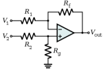
"Fabbing test gear"? You said your meter had an unbalanced input? I just thought a simple op amp to un-balance things would be handy? Powered from a pair of PP3s it would also avoid hum loops. I have a Wayne Kerr Radford noise meter so powered although I use two packs of 6 AAs as the meter is quite hungry!
I have attached a simple schematic, all the Rs would be 10k. The noise performance will not be state of art but would be below -100dBu, more than good enough for tape!
Dave.
Yes, -10dBV is fine, I was thinking "digital" where an internal level of -2dBu give about the best compromise between noise and headroom (about +22dBu for the latter)
"Fabbing test gear"? You said your meter had an unbalanced input? I just thought a simple op amp to un-balance things would be handy? Powered from a pair of PP3s it would also avoid hum loops. I have a Wayne Kerr Radford noise meter so powered although I use two packs of 6 AAs as the meter is quite hungry!
I have attached a simple schematic, all the Rs would be 10k. The noise performance will not be state of art but would be below -100dBu, more than good enough for tape!
Dave.
Attachments
I am not sure this is the right place for my question, but let me ask :
My TASCAM 388 have a problem : the right output does not work except when I put the MONO switch ON or with a signal into the right buss directly on the back panel.
Any idea on what could be the problem ?
Thank you for your help, if any ;-)
My TASCAM 388 have a problem : the right output does not work except when I put the MONO switch ON or with a signal into the right buss directly on the back panel.
Any idea on what could be the problem ?
Thank you for your help, if any ;-)
sweetbeats
Reel deep thoughts...
I am not sure this is the right place for my question, but let me ask :
My TASCAM 388 have a problem : the right output does not work except when I put the MONO switch ON or with a signal into the right buss directly on the back panel.
Any idea on what could be the problem ?
Thank you for your help, if any ;-)
Could a moderator move the posts previous and subsequent to this post to a new thread so obi91 gets the most exposure for assistance and so others can benefit?
Last edited:
I have "fixed" my " no signal on the RIGHT channel output " problem ;-)
well, I was able to make my right channel working again this morning, by accident !!
I was trying to fix my " no signal to the right output, exept in MONO or with signal injected directly to the RIGHT BUS".
I have apply by accident a very high level signal ( I was playing a piano sound from an expander ) and sound started to appear on the right channel, but scratchy, like there was a fals contact or a dirty pot ... I continue to apply my piano signal more and more lound and finaly, the right channel signal came back normal ...
OK I still have to look in the schematics what could cause this scratchy effect on the right channel but now, my Tascam 388 is back to normal operation ... which is cool ;-)
This might help someone ... hopefully ;-)
sweetbeats
Reel deep thoughts...
So, while I wait for my acquaintance to reverse-engineer the EQ board so I can nail down what conservative upgrades or modifications are going to be employed there, I’ve started in on the first step of the line output amp redesign. Again, a very benevolent and smart person took it upon himself to bluntly but congenially tell me, after expert analysis, the high headroom line amps in the M-__, the ones used for the balanced main L-R and unbalanced buss outs on modules 1-12 (which can be balanced by stuffing the components into the vacant sites on the buss amp board), are pretty much worthless, “like the outputs in so many other consoles”, for driving low-impedance loads, particularly transformer isolated loads...which pretty much describes the inputs on my Ampex MM-1000. Bummer. Under those conditions the Teac line amp will lose steam primarily resulting in completely unusable distortion levels, and poor LF response. But in the same breath my acquaintance said, in the spirit of The 6 Million Dollar Man, “It can be made to be more than adequate, even superior.”
So for some unknown reason this Oscar Goldman type fella is mentoring me through the circuit changes, testing and refining of the circuit. I’m thankful for the mentoring and enjoying learning and transforming the circuit into something more usable for my application. Reminder: this is the same circuit as found in the 2-channel balance amp section of the M-50 mixing console. That’s the only other Teac product in which I’m aware it was used. It is powered by very high +/-35V power for exceptional headroom, but falls short of the mark with low impedance loads. I wonder if this is part of why it wasn’t used elsewhere (poor low impedance performance), or it was too expensive to mass produce...there are similar circuits in the LA-40 and Tascam 58 balanced output line amps, but the circuit is a simplified (less capable) version and powered by lower headroom voltage rails (+/-20V).
But it is a pretty unique circuit for a Teac device I believe. Another super smart guy said this of the circuit:
“the Tascam [prototype console] has a semi-discrete opamp / BJT line amp. The opamp drives a complementary 69 pair running with gain and with high rail voltages for headroom. It's not at all what I'd expect from them, but there it is. It is definitely not a naked 4558 driving an RCA jack.”
My mentor in this project recently commented that this project, when complete, will outfit the M-__ with “...line drivers equal to or better than anything sold by the high dollar "snoot" brands...”
A couple of the best parts about this project is it doesn’t cost much (maybe about $15 in parts in quantity per balanced output), and its not a wild modification project...it is essentially upgrading parts tolerance and quality, tuning values, and using different output transistors. The design also achieves essentially zero DC offset eliminating the output coupling capacitors. A vastly improved power supply design is being implemented...the stock supply in the M-50 is a simple unregulated design. I’ll be incorporating a precision regulated supply receiving juice from a transformer rated at 2A at 70V...plenty of oomph. And no traces need to be modified on the line driver PCB...no jumper wires all over the place...no crazy kludges. The board will appear essentially stock except for new parts. That’s the coolest thing to me...The essential design of the circuit and board layout is okay...we are simply improving the parts selection, and tuning and refining the circuit around the improved output transistors for significant real-world improvement pertinent to the application...the latter being the key part of the project and one requiring expertise far beyond mine. The power output potential and headroom of this line driver design is *total* overkill, but I’m pressing forward because “it’s there” and I want the M-__ to be all it can be and all it might have been.
I think the line out driver and the “REMOTE” source switching functions of the console are really two of the key defining features of the console.
So, step 1 is to gut one of my spare M-50 line driver PCBs, stuff with new parts as advised including trimmable bias resistors so we can tune the bias network. Here are some pics of a stock board next to the gutted and prepped board, and then the two next to each other after some progress building up the test assembly:


Once the assembly is complete there will be a specific procedure to follow for power up, then bias network tuning, and then power testing with distortion analysis and I expect further tweaks.


So for some unknown reason this Oscar Goldman type fella is mentoring me through the circuit changes, testing and refining of the circuit. I’m thankful for the mentoring and enjoying learning and transforming the circuit into something more usable for my application. Reminder: this is the same circuit as found in the 2-channel balance amp section of the M-50 mixing console. That’s the only other Teac product in which I’m aware it was used. It is powered by very high +/-35V power for exceptional headroom, but falls short of the mark with low impedance loads. I wonder if this is part of why it wasn’t used elsewhere (poor low impedance performance), or it was too expensive to mass produce...there are similar circuits in the LA-40 and Tascam 58 balanced output line amps, but the circuit is a simplified (less capable) version and powered by lower headroom voltage rails (+/-20V).
But it is a pretty unique circuit for a Teac device I believe. Another super smart guy said this of the circuit:
“the Tascam [prototype console] has a semi-discrete opamp / BJT line amp. The opamp drives a complementary 69 pair running with gain and with high rail voltages for headroom. It's not at all what I'd expect from them, but there it is. It is definitely not a naked 4558 driving an RCA jack.”
My mentor in this project recently commented that this project, when complete, will outfit the M-__ with “...line drivers equal to or better than anything sold by the high dollar "snoot" brands...”
A couple of the best parts about this project is it doesn’t cost much (maybe about $15 in parts in quantity per balanced output), and its not a wild modification project...it is essentially upgrading parts tolerance and quality, tuning values, and using different output transistors. The design also achieves essentially zero DC offset eliminating the output coupling capacitors. A vastly improved power supply design is being implemented...the stock supply in the M-50 is a simple unregulated design. I’ll be incorporating a precision regulated supply receiving juice from a transformer rated at 2A at 70V...plenty of oomph. And no traces need to be modified on the line driver PCB...no jumper wires all over the place...no crazy kludges. The board will appear essentially stock except for new parts. That’s the coolest thing to me...The essential design of the circuit and board layout is okay...we are simply improving the parts selection, and tuning and refining the circuit around the improved output transistors for significant real-world improvement pertinent to the application...the latter being the key part of the project and one requiring expertise far beyond mine. The power output potential and headroom of this line driver design is *total* overkill, but I’m pressing forward because “it’s there” and I want the M-__ to be all it can be and all it might have been.
I think the line out driver and the “REMOTE” source switching functions of the console are really two of the key defining features of the console.
So, step 1 is to gut one of my spare M-50 line driver PCBs, stuff with new parts as advised including trimmable bias resistors so we can tune the bias network. Here are some pics of a stock board next to the gutted and prepped board, and then the two next to each other after some progress building up the test assembly:
Once the assembly is complete there will be a specific procedure to follow for power up, then bias network tuning, and then power testing with distortion analysis and I expect further tweaks.
You are a glutton for punishment Sweetbeats! I confess I would never go to so much trouble.
I would go the easy route and use LM4562s as balanced outputs which would have a headroom of at least +26dBV (+28dBu) and comfortably drive down to below 600 Ohms with +-17V rails. I doubt discrete devices will better that even at 70volts? The LM OP stage could be configured as 'zero impedance' as per D.Self.
I have a deep distrust of DC coupled OP stages, fixed too many amps that have gone 'offset apeshit'! Especially with tape recording which cannot get close to DC. Again, Mr Self shows a way to have a near zero OPZ and put the coupling cap in the feedback loop.
Still! THAT's ^ just me! All power to your elbow Mr S! Love to see the finished schematics.
Just thought? If those OP stages are feeding a transformer and a transistor DID fail I doubt the traff would survive?
Dave.
sweetbeats
Reel deep thoughts...
You are a glutton for punishment Sweetbeats! I confess I would never go to so much trouble.
I would go the easy route and use LM4562s as balanced outputs which would have a headroom of at least +26dBV (+28dBu) and comfortably drive down to below 600 Ohms with +-17V rails. I doubt discrete devices will better that even at 70volts? The LM OP stage could be configured as 'zero impedance' as per D.Self.
I have a deep distrust of DC coupled OP stages, fixed too many amps that have gone 'offset apeshit'! Especially with tape recording which cannot get close to DC. Again, Mr Self shows a way to have a near zero OPZ and put the coupling cap in the feedback loop.
Still! THAT's ^ just me! All power to your elbow Mr S! Love to see the finished schematics.
Just thought? If those OP stages are feeding a transformer and a transistor DID fail I doubt the traff would survive?
Dave.
Dave, I appreciate your thoughts.
The semi-discrete line driver will be capable of excellent distortion and frequency response specs even down to 50R at +31dB...that’s as high as 15W...+35.5dB @ 600R. This is important because I’ll be driving transformer-coupled 600R nominal impedance loads, but I’m told the greatest demands on power happen at the fringes of the audio spectrum, and transformers are not constant impedance devices and tend to drop off at the ends of the spectrum. So the amp *could* see loads as low as 50R and transient peaks in the upper twenties (dB). Yes that is complete overkill...maybe...but your example with the LM4562 would have that part operating at or near maximums. With the 4562, and output current at +28dBu @ 600R...isn’t that at or near the 4562’s limit at 600R when in the real world it may actually be seeing lower impedances? Why would I want to employ a circuit that pushes the limits of the part? No I’m not going to be pushing sine waves at +28dBu, but kick and snare drum transient peaks surely poke those levels and I’d rather something unwavered by those levels and impedances be pushing signal rather than something that’s reaching or exceeding maximums. With the LM4562 example it would be breaking up with those transient peaks at the ends of the spectrum into that non-constant low impedance load. Easier yes. But even the stock line driver sounds really nice to my ears. We’re going to make a circuit that maintains “really nice” to the limits under real-world interfacing to a low-impedance transformer coupled load. I want to make sure it’s the tape on the machine doing “stuff” to those maximums and not my line drivers breaking up. The Ampex input amps will handle those levels just fine, and now the line outs on the console will be able to play in the same league. It should be pretty nice.
Hello Sweetbeats. Now this is difficult! I don't want to come across as some 'know all A'hole that is questioning their betters but I am struggling to see the logic here? I am also NOT questioning the grand efforts you are putting in to restore this fine old equipment. But, might I try your patience just a little longer please?
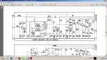
I cannot find a schematic for the record amplifier that shows an input transformer. The one attached shows an unbalanced emitter follower (of pretty cooking design!) and I would estimate the input Z to be no less than 100k and not frequency dependant. If that circuit had an input transformer I would expect it to be a 10k-10k line 'bridging' type, it would also almost certainly have a 'Zobel' CR network across it.
Of course I may have completely the wrong schematic.
Transformers do not have variable impedances at frequency extremes unless, at VLF their inductance is too low (poor design choice) and at VHF they have excessive interwinding capacitance again, poor design.
Forgive me, I know YOU know this but a 1:1 transformer has an input Z equal to the secondary load if operated at its design limits.
For the now rare beasts, 600-600 Ohm INPUT transformer I found the Cinemag CMLI-600 as an example and that has excellent distortion performance down to 20Hz and +14dBu. A transformer capable of handling 15W at low frequencies would have to be the size of the OPT in a Fender Champ, bigger actually since the Champ is hardly 'Hi Fi'!
Can I repeat good sir, that I am not criticizing anyone, just cannot see why a company like Ampex should design such a demanding input stage?
Dave.
Attachments
sweetbeats
Reel deep thoughts...
I don't know, man...you know a LOT more about this stuff than I do. All I know in this is what I'm told by folks who design this stuff and know the Ampex machines that are helping me.
Anyway, your schematic you are only looking at is the schematic for the plug-in record amp card only for the AG-440/MM-1000 electronics. You aren't seeing the rest of the electronics module. Here's the rest of it:
http://torridheatstudios.com/documents/Ampex/Ampex%20440%20Electronics%20Schematic.pdf