Tascam M-___ Story...

technoplayer...

WAY COOL!

I'm out of town right now, but I'll check that when I'm back in town.

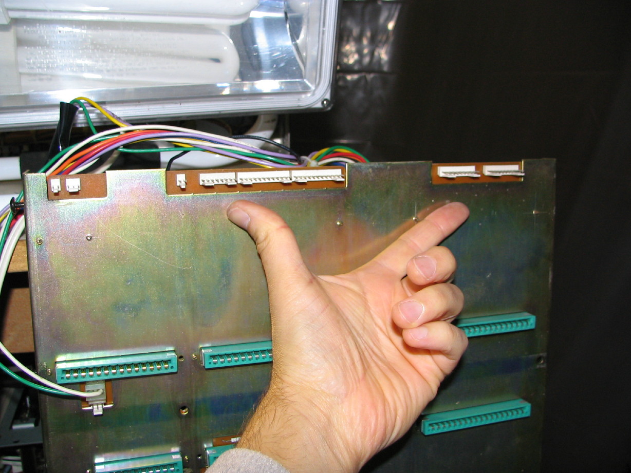
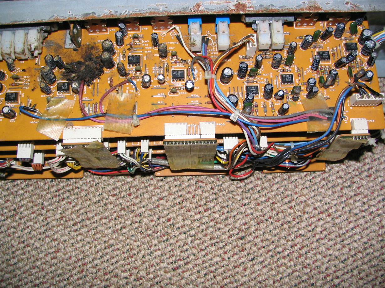
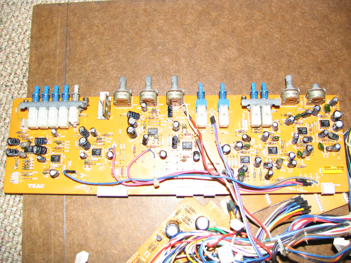
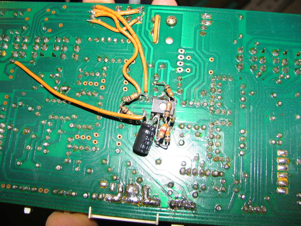
I think you're right that the chips have not been replaced. I'll look on the trace side to see if I can see any evidence of that...

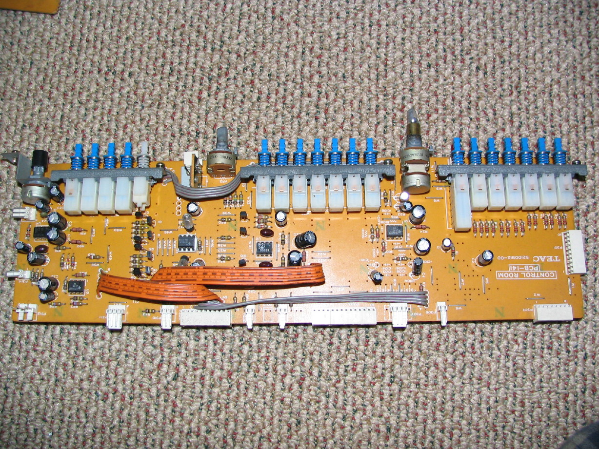
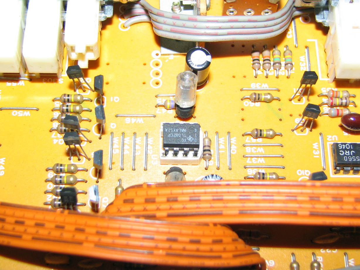
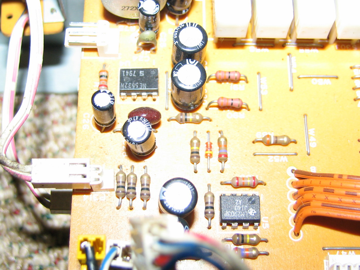
You're also right that most of the 072 chips are JRC, and only one is TI. Weird...but anyway, I'll check that date reference and post it up.

Cool! Thanks! ;)
 
Wowwwww!

Thanks for thinking of me...That is a truly interesting piece of gear...Never heard of it. Thanks for sharing, and glad you are enjoying the thread! ;)
 
More data

I noticed that those same TI op amps are on the sh**ed up board, and I read the code as J140. This is odd, as it does not follow the current marking conventions.

I actually contacted the engineer who authored TI's Semiconductor Marking Guidelines document, and he is not even familiar with the coding, so it is ...old. Here is what I've worked out.

> The TL078 family dates from the late 70's, although it is still in production today.

> The boards have virtually no other IC's on them except for the JRC chips.
I do not know when Tascam started using IC's vs discrete components on a wider basis, but this points to an early adopter of IC technology. Op amps were one of the big application IC's in the 70's

> TI chips after about 1990 were laser symbolized, whereas the chip on your board is ink symbolized. This suggests a chip mfg between about 1978 and prior to 1990.

> Chips often also contain Country of Origin markings

> I am thinking you have a chip made in a TI Japan (J) fab in the 40th week of 1981

This might suggest a console build in 1981-1982 time frame.
I believe this pre-dates the M520 series by a few years, so this may be a prototype for that series.
 
Some more IC specifics...

So I took a closer look at both the channel card IC's, and what I could see at this point of the master section IC's (I haven't pulled that apart yet).

Aside from the two Motorola logic chips mentioned a number of posts back, almost all the IC's are indeed JRC chips. And of those JRC chips nearly all are 072D's save for a couple 4556D's. Yes, I said "almost" all the IC's are JRC's...there are two TI chips. One is the one noted above on the eq PCB, the TL072D with the J140 X2 code on it. The other is on the channel mother PCB (I called this the AUX/MONI PCB above, but it really is like a mother card for the set of 6 channel PCB's)...it is an LM393P, which also has a J140 code with an "A2" suffix. So that's interesting to me. The TI TL072D chip on the EQ board looks like a retrofit! It is the same chip on the other channels, but I won't be able to see the trace side of the EQ boards until I start pulling the other channels apart. The LM393P looks like an original install.

I decided to look at the INPUT PCB's for my M-520, and those also are mostly JRC chips with a couple TI's.

Why would they use some of one brand and some of another? If the TI chip on the EQ board on the M-___ console was originally a JRC, why retrofit a TI chip of the same family?

I also logged the pot types and compared with those of the M-520 to see if I would find M-___ spares among my M-520 spares. Very little in common. Lots of different types on the M-___. Of the 16 pots (single and stacked) on the M-___, there are 12 different types, 2 of which are common to the M-520 (and they are single pots).

Picked up some paint today for the frame. I don't own an air sprayer, and this oil-based enamel is going to take some time in between coats to dry so I didn't want to rent anything. I found a cool thingy...its a glass bottle to which a disposable propellant can attaches. Pour the paint in the bottle, screw on the propellant can and spray custom paint color with the convenience of a rattle can.
 
This is really interesting to me...

I opened up the fader for channel 1. There's a lot going on inside these faders. Looks like they could do lots of things. Don't know what, but there's several unused terminals and tracks.

It is really clean in there...maybe they don't wear much, but it struck me as looking almost new...

Fader%20(internal).JPG
 
Last edited:
...I found a cool thingy...its a glass bottle to which a disposable propellant can attaches. Pour the paint in the bottle, screw on the propellant can and spray custom paint color with the convenience of a rattle can.

Yep, a Prevail Sprayer. Guitar refinishers and car-lot detailers are all familiar with that nifty little device. Replacement propellent canisters are available, too.

I first used one with Nytro-cellulose lacquer poured directly from the can, on the neck of a Strat I rebuilt. Worked like a charm!
 
Painting, painting, painting...

I tried that little Prevail sprayer...didn't work. The enamel is too thick draw for the propellant canister, and the paint says "Do Not Thin". :( 
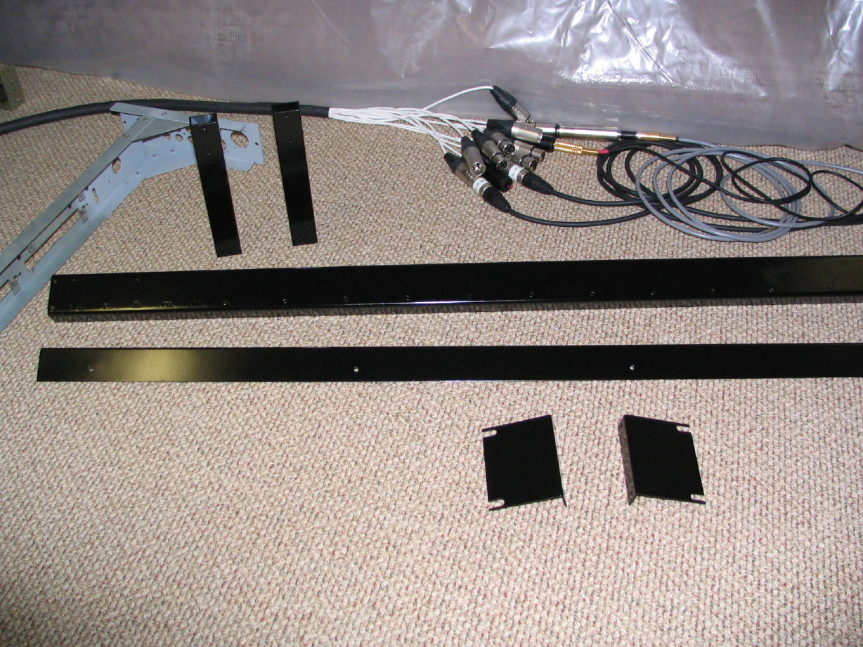
So I did the next best thing; I rolled the paint on. :eek: Honestly, it worked pretty well. I used a 4" foam roller, and because the paint is an oil-based enamel it takes a long time to dry, which is nice in this case because it levels out nice. Its actually got kind of a hammered finish but it is stock color, which is what I wanted. This paint is very durable. Its supposed to be used on, like, farm implements and stuff.
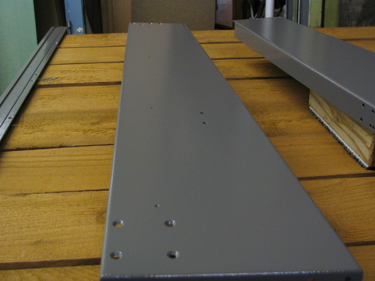
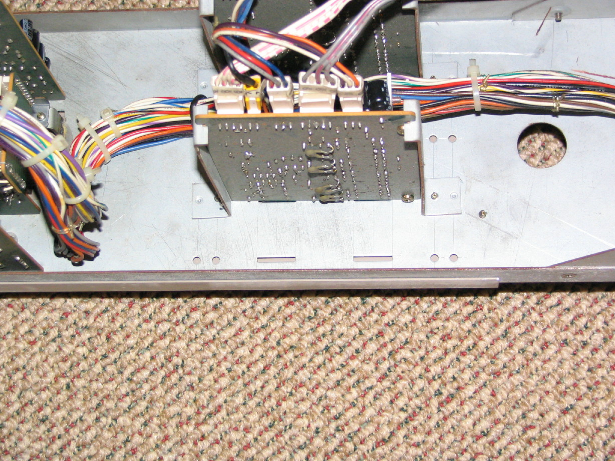
Freshly%20Painted%20Frame%20Sections.JPG


I also finished painting all the black internal structural members that were either badly scratched or peed and pooped on by rodents...Used a wire brush (hand) and a chuck-mounted wire-wheel on a hand-drill...sanded with 220-grit, primered and then three coats of fast-dry gloss-black Krylon...no sanding in-between.

Here are the meter bridge uprights, the rear cross-member and the upper rear dress panel (a couple rack ears for a PB-64 that were badly scratched also in the foreground also...), and in the background you can see the frame for channel #1...All the mouse yuck was washed out, rust scraped out with the wire wheel, and then some selective shots of gray primer...the mouse yuck is gone...except for the pile on the Master Module. :rolleyes: One of those uprights was badly pitted and thickly rusted from the mouse waste.

Freshly%20Painted%20Black%20Things.JPG
 
Last edited:
Why would they use some of one brand and some of another? If the TI chip on the EQ board on the M-___ console was originally a JRC, why retrofit a TI chip of the same family?

The TI chips are what are referred to as catalog parts. You can still buy that exact same chip today, 28 years later. The JRC chips are and were probably unobtainable in the US.

Mixing brands may be a matter of both cost and functiionality. Chips cost a lot more in that era, so I wouild imagine Tascam made big quantity purchases of the JRC chips, since, after all, they were building this stuff in Japan. Not knowing exactly what the JRC's are, they may have been made to spec for Tascam as well.

In any case, all I was trying to do was narrow down the mfg date of your M-xxx
 
Is it possible that all of the traces inside that fader were used with some type of automation system?

I've never personally gutted an automation-powered fader, but who knows? Is it completely off-the-wall to say that this mixer has capabilities of interfacing with an automation system? Or perhaps.... that the faders were pulled from a board that HAD automation, and they never got around to adding automation to it?

Or am I just crazy to say that, and is this not even a fader capable of automation?
 
Maybe...

Maybe they needed all the parallel and partial traces to make the fader impedance specifically what it is, by design.[????]:eek:;)
 
Is it possible that all of the traces inside that fader were used with some type of automation system?

I've never personally gutted an automation-powered fader, but who knows? Is it completely off-the-wall to say that this mixer has capabilities of interfacing with an automation system? Or perhaps.... that the faders were pulled from a board that HAD automation, and they never got around to adding automation to it?

Or am I just crazy to say that, and is this not even a fader capable of automation?

well inquiring minds want to know...

possible but not likely... those interupted traces look kinda like pads for contact switches... but why then have the other traces (the brown painted ones) i'm assuming they are traces... the 2 sets of long traces could have maybe been used if the fader were motorized... the audio goes through one trace... the other trace would then have a reference voltage placed across it... which is devided by the placement on the trace and memorized in some fashion so it could be repositioned... but not likely on this board... more likely the oem of the fader used this board for several models and the extra traces are for other models...
 
Thus begins a stretch of posts of new and interesting info and updates...watch out!

more likely the oem of the fader used this board for several models and the extra traces are for other models

demented...I think you're right...It is an ALPS fader BTW. I have a hunch they wanted a good quality fader for the prototype and they pulled off the shelf what fit the bill. That ideaology is found in other places on the board. I was dialoguing with Ethan and he noted that some of the passive components (some of the non-electrolytic caps specifically) were higher-end choices for the day.

I think some of the other traces exist because (I think) these are actually stereo (capable) faders.

Check this out...this is the STEREO MASTER fader opened up...its the same fader with a different configuration (this is the fader the mouse/mice peed all over...the inside looks good though and the outside is cleaning up okay):

Master%20Fader.JPG


What do you guys use to lube faders (not the trace, but the shaft)?

So there are all sorts of designed-in non-utilized features that I'm noticing like the fader thing (extra traces/contact pads)...remember way back up toward the the top of the thread when I pulled the channel module out and noticed that there were blanks in the jack plate for other larger connectors like XLR connectors? Threre are whole unused sections on a couple of the channel PCB's...maybe for stereo channels? Its cool.

I'm thinking the contact pads on the fader boards might be for automating startup of other devices...My BR-20T can be fitted with the capability for the transport to engage based on the fader position of a so-equipped console (the transport jumps into action when the fader is raised above infinity...that sort of thing).

And check this out...I forgot to mention this a couple weeks ago.

The mother PCB's have multipin connectors at each of their ends...these connectors extend all the buss, aux and remote traces on the mother PCB's along with all the voltage rails...cascade connectors ala M-35 ~ M-35EX???

Here is a picture of one end of the connectors as indicated by my thumb and forefinger:

Mother%20PCB%20Cascade%20Connectors.JPG
 
Last edited:
For technoplayer

This might suggest a console build in 1981-1982 time frame.
I believe this pre-dates the M520 series by a few years, so this may be a prototype for that series.

Techno...thanks again for the info. I think you are right about 1981 ~ 1982. That ties in with the color scheme (the orange accents on the fader trim strip) and I realized that the lower knob cap on the stacked pots is the MX-80 variety, not the M-500 type so I'm assuming it pre-dates the M-500 boards...That time period would also have it as being built before anybody who is presently at Tascam started working there, further explaining why nobody knows about it.

I've kind of wondered if this was an idea that ended branching into the M-500 and M-600 consoles, though the M-600 boards came out much later (later 80's and the M-500's came out early-mid 80's). The color scheme and silk-screening are pure 500-series lookin', as is the aux and pgm buss topology, but the modular channels and enhanced routing features are more M-600 (channel frame design from the model 15)...almost like it was supposed to be a new model 15, or the next iteration of it, but the market got steered to the gap that the 500-series filled. Its a total hybrid really...small format, cascadeable, modular, advanced routing and bussing features...

blahblahblah...:rolleyes:
 
If ever there was a question about this being a prototype board...

I think I can drive the nail in that coffin.

Decided to pull the master section apart and start cleaning that last night...needing to get some additional info on what all the 35V rails drive and I figured I could knock out two tasks; cleaning it up and getting into what's on those other boards in the master section.

I saw from underneath, up by the two balance amp PCB's, more scribed marks and hand-cut holes:

Master%20Panel%20Scribed%20Holes.JPG


Then I pulled the dress panel off and look


what


was


underneath:

Master%20Panel%20Red%20Ink%20%231.JPG


Hand-written dress panel...:eek:...presumably there to assist engineering/R&D prior to the dress panel being fabbed??? :eek:

Here's a series of three closer-up pictures from the top down:

Master%20Panel%20Red%20Ink%20%232.JPG


Master%20Panel%20Red%20Ink%20%233.JPG


Master%20Panel%20Red%20Ink%20%234.JPG


Notice all the switch-rack mounting brackets are hand-fabbed brazed on mounts...in fact, every hole/notch/bracket on this frame is hand-built! :eek:

Prototype? :rolleyes::p
 
Last edited:
Poop & Pee B-Gone

Dave, finish your coffee first, then proceed. :D

Okay, if you've read this far, then you know some mouse used the MONITOR MASTER PCB as a bathroom.

Got some PCB cleaner and, after an extended duration using a paintbrush and a toothbrush, I got it to go from this:

Monitor%20Master%20PCB%20Before.JPG


to this:

Monitor%20Master%20PCB%20After.JPG


I'm assuming that I should probably, at the very least, remove and replace components that were either in or proximal to the main pile. Anybody wanna weigh in on that?
 
Last edited:
More PCB's

Cleaned up the rest of the master section boards (with PCB cleaner, and then applied DeoxIT to all switches and pots). Here's what they look like (in order as they are mounted left to right looking at the face of the master section...there are 4 total, and #4 is the MONITOR MASTER PCB you've already seen...):

TALKBACK PCB
Talkback%20PCB.JPG


STUDIO PCB
Studio%20PCB.JPG


CONTROL ROOM PCB
Control%20Room%20PCB.JPG


Did you notice that there is a socketed IC on that last one? Interesting...Here is a closeup of the chip:

Control%20Room%20PCB%20Socketed%20IC.JPG


And here's what's on the trace-side of that socketed IC:

Control%20Room%20PCB%20Socketed%20IC%20Trace-Side.JPG


Maybe THAT'S the strongest evidence that this is a prototype unit...:eek:

Pretty much all the IC's in the master section are what you'd expect...either 072's, 2041's, 4556's, etc. And there's another one of those Motorola logic chips as well, but the CONTROL ROOM PCB has a couple other opamps too:

Control%20Room%20PCB%20Additional%20IC's.JPG


That's all I have on that topic for now.
 
Last edited:
Back
Top