A Reel Person
It's Too Funky in Here!!!
You are an Animal! Gearslutz rejoice! Here's our Mentor!
Heh, heh......
")
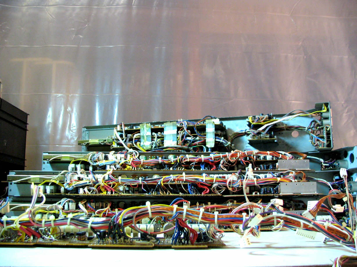
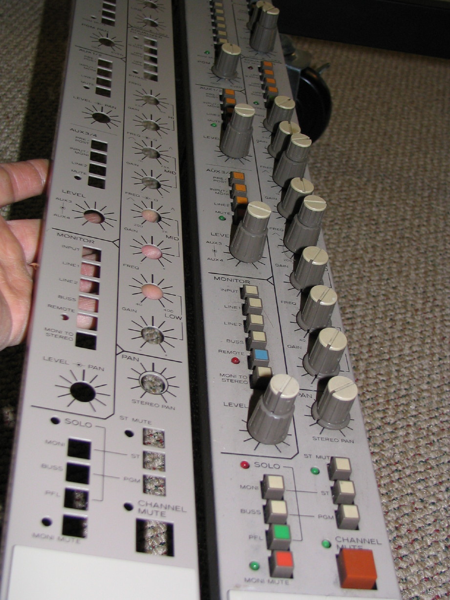
Hey, that's a pretty sharp and impressive looking board! Fully loaded, no doubt.
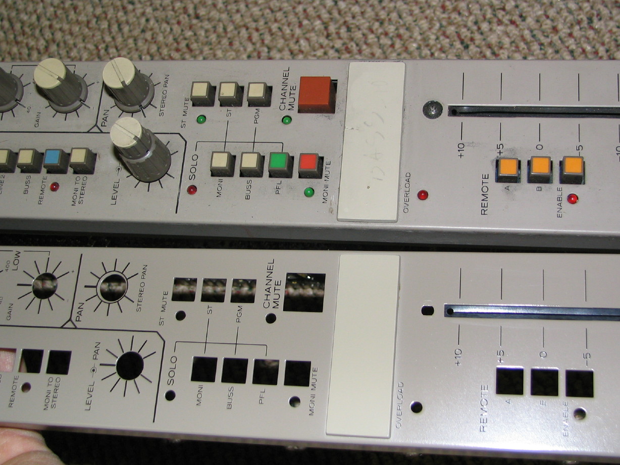
I guess you got more than you were bargaining for in the Master section! Blecchh! Did I have to view that with my morning coffee? Aaaggghhh!!!
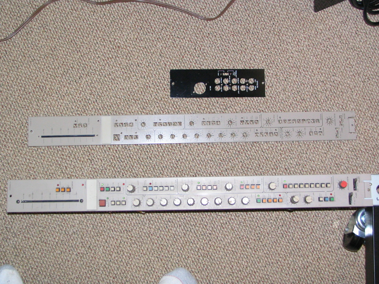
All those nifty PCB's and no formal part numbers? Screw holes scribed and drilled by hand? Of course it's a prototype, now c'mon!
Not just a prototype, but IMO a legitimate piece of history!
Too bad I missed you on the Burbank run. It would have been fun to meet you down there for the pickup. Plus, there's Pro-1 AV, a great recording specialty shop down there that I could've shown you! Well, next time!
Question: If I decided to give up all my gear, would you come down with a U-Haul and pick it up??? Never mind, I think I know the answer!
Heh, heh......
Hey, that's a pretty sharp and impressive looking board! Fully loaded, no doubt.
I guess you got more than you were bargaining for in the Master section! Blecchh! Did I have to view that with my morning coffee? Aaaggghhh!!!
All those nifty PCB's and no formal part numbers? Screw holes scribed and drilled by hand? Of course it's a prototype, now c'mon!
Not just a prototype, but IMO a legitimate piece of history!
Too bad I missed you on the Burbank run. It would have been fun to meet you down there for the pickup. Plus, there's Pro-1 AV, a great recording specialty shop down there that I could've shown you! Well, next time!
Question: If I decided to give up all my gear, would you come down with a U-Haul and pick it up???
Never mind, I think I know the answer!

 :rolleyes:")

")
/Input%20PCB%20(Component-Side%2c%20small).jpg)
/Input%20PCB%20(Trace-Side%2c%20small).jpg)

/PGM%20PCB%20(Component-Side%2c%20small).jpg)
/PGM%20PCB%20(Trace-Side%2c%20small).jpg)
/EQ%20PCB%20(Component-Side%2c%20small).jpg)
/EQ%20PCB%20(Trace-Side%2c%20small).jpg)
/AUX-MONI%20PCB%20(Component-Side%2c%20small).jpg)
/AUX-MONI%20PCB%20(Trace-Side%2c%20small).jpg)
/MUTE-SOLO%20PCB%20(Component-Side%2c%20small).jpg)
/MUTE-SOLO%20PCB%20(Trace-Side%2c%20small).jpg)
/REMOTE%20PCB%20(Component-Side%2c%20small).jpg)
/REMOTE%20PCB%20(Trace%20Side%2c%20small).jpg)