Tascam 312B Project

Yes you have to power both +/-15VDC power rails to test audio.

But back up.

You are looking at AC power supplies? For what?

If you are looking for a bench power supply, don’t worry about that right now. Get those clip leads/jumpers I linked earlier. You are going to use those to connect the PCB to power while it’s out of the mixer...but you’ll just connect it to the mixer’s power supply...you’re using the jumpers like extender cables.

If you *did* power the PCB with something besides the mixer’s power supply you would have (a) DC bench supply(ies). These come in many forms and flavors. I have a couple different ones on hand at the moment, a dual 0-50VDC variable current limiting bench supply, and another that produces fixed 12VDC, 5VDC, and variable 0-30VDC. But guess what you use to connect the bench supply to the PCB? That’s right...jumpers, clip leads, etc.
 
If you are looking for a bench power supply, don’t worry about that right now. Get those clip leads/jumpers I linked earlier. You are going to use those to connect the PCB to power while it’s out of the mixer...but you’ll just connect it to the mixer’s power supply...you’re using the jumpers like extender cables.
Those clip leads should be here this week. I was thinking more of when I wanted to keep my mixer in one piece and wanted to do the troubleshooting on those other boards.
I guess I’m getting confused on things.... some of the things I have are low voltage AC... The 312 block diagram said AC power supply circuit.. that’s why I was thinking an AC power supply. So those boards are powered +/- 15 VDC AND +6VDC ???
 
You’ll have to point me to where the manual says AC power supply. The mains power is AC, but the power supply converts that to DC power...+/-15V for audio, +6V for the headphone amp and the VU meter lamps, and +48V for phantom power. You only really need the +/-15V to bench test/troubleshoot any of the audio boards. You could even run them off of +/-12V.

There are tons of options for power supplies. Current limiting is always nice (that’s where the power supply will only provide power up to a certain current flow, so when your like me and you “cross the streams” and try to set something on fire the power supply sez “nope”. But a new basic git’ ‘er dun +/-15V supply looks like this:

60w dual output switching power supply 15v 2a,-15v 2a D-60F15 China Supplier | eBay

Spending around $100 gets you a couple single output variable supplies that might be current limited.
 
One of the other things I have been doing is building my "studio".... I say that with a chuckle because it really is a multipurpose room. My goal was to make it sound the best that I could with a limited budget and all, plus make a game room area (afterall..... this is HOMErecording right??? :D ). well I think I pretty much accomplished what I was after. Here are the before and after pics:
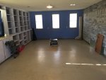

File Nov 30, 7 42 03 AM.jpeg
File Nov 30, 9 11 20 AM.jpeg

More pics are here https://homerecording.com/bbs/general-discussions/studio-building-and-acoustic-treatment/i-dont-want-studio-i-want-bradland-392373/7/#post4472447

alright.... I'm through patting myself on the back.... time to install that monitor card!!!!
 
Alright.... back to the mixer...... I acquired another monitor board as a spare/replacement so while I am waiting for the chip sockets to get here for the original board, I thought I'd install it to get the mixer going. .......I'll tell you, solder sucking is getting easier......... Well I installed it, and the good news is all the monitor section now works!! Great test signal through all the auxs, effects, stereo, mono, all the exts...everything clear as a bell.... I was pumped!!!!!!

......and then...........

.......I noticed..........

....the L and R meters were not moving....... Shoot!!!! They were moving before.

My first thought was operator error. so I went to the manual to the calibration section and did the steps in the "Calibrating The 300 Series Mixers For Recording" section of the manual....... The meters still weren't functioning...

I next measured for DC offset(?) at pins 1 and 2 of P405 on the monitor board (the L/R meter connection). No change from when I first measured without the signal and then when I measured with the signal. Now I've never done the DC offset thing before, so I ought to tell y'all how I did it in case I did something wrong. first I set the mixer up like described in the "Calibrating The 300 Series Mixers For Recording" section of the manual. Then I:
1. Turned on the 312
2. Turned the DC meter to millivolts
3. Measured voltages on pins 1,2 of P405 (Pin 1 was 5mV Pin 2 was 13mV). The way I measured was the red lead of the meter was on the pin, and the black lead was on the GND of the BUSS PCB.
4. Injected a signal into the line in of channel 8 (as described in the manual) re measured pins 1 and 2. the voltages were the same.

I also set the meter to milliamps and did the same thing trying to measure any current with no change....... so I went to my WWSBD thoughts and went to the block diagrams and schematics..... and herein lies the problem....... There is nothing between the monitor switches the meter switches or the meter switches and those two meter pins except traces.... Now in my mind, I can't believe all the meter functions would go bad....

Admittedly, I have not unsoldered the board to take a better look since everything works but the meters.

I guess my question are : Am I missing something? Did I do my measurements right?
 
Disconnect J405 from P405 of the MONITOR PCB and find a way to inject tone to either pin 1 or pin 2 of J405. Your signal lead from your tone generator goes to pin 1 or pin 2, and the ground you can clip to the outside of any of the RCA jacks on the back (that’s signal ground). Can you get the L or R meters to move?

Double check your connections to the L-R meter amp PCB, the board to which the L-R meters are attached.
 
Last edited:
The point here is we can test DC offset and try and calibrate the meters all day, but if signal isn’t getting to P405 and/or the meter amp isn’t working (for any number of reasons) we need to address that first. So I’m starting with bypassing the monitor board and injecting tone or signal straight to the meter amp (signal to pin 1 or pin 2 of J405).

Good job identifying there’s nothing in between the meter source select switches and P405, except for some traces and solder joints, and unless every solder joint went bad or the board is cracked, if you are getting good signal at the monitor out jacks and in the headphones, well, the monitor source switches and the meter source switches get their goods from the same place and there’s nothing in between except for a bunch of traces and solder joints. So that’s why I’m jumping to “let’s see if the meters work”. You could also confirm, just to be sure, there is good signal at P405. Just assign tone to the main buss, select STEREO in the meter source select switchrack, put the negative probe of your multimeter on the outside shell of any of the RCA out jacks, and your positive probe on pin 1 or pin 2 of P405...meter set to AC volts (remember, audio signal manifests as AC voltage). If you’ve got signal at pins 1 and 2 of P405, and you have good continuity from J405 up the meter amp board (again, the meter amp is on the PCB to which the L-R meters are mounted), but you can’t make those meters move by injecting tone directly to J405, then there is a problem with the meter amp. If that’s the case I’d start by getting the back of the meter amp PCB exposed and verifying you’ve got power at the board (its +/-15V), and good ground continuity.

Your recording/music space looks great by the way. Has a nice character to it and looks very usable. :D

I’m in the midst of converting a 24 x 24 unfinished detached garage to finished multi-use space...exercise equipment, games, musical instruments and recording equipment...and...an antique pool table that’s been in the family for generations. I laughed when I saw the pool table in yours. :thumbs up:
 
Thanks for the tips.... We are heading off on a two week venture, so I’m going to have to wait a bit to try that. The other reason for waiting is I have a feeling I can make a lot of test leads out of phono plugs soon to run my test signal to pins......

It seems somebody recently bought a second patchbay thinking it had a bunch of phono plugs..... it had a bunch of RCA plugs...... too many patchbays on the watchlist, and I pulled the trigger on the wrong one..... I was wondering why it was so cheap..... anyway, I think I’m going to run my inserts through it. I had already bought a phono plug insert snake, so it looks like after Christmas, I’m going to be replacing phono plugs with RCA plugs.....good soldering practice....so I hear.... :D

I love the room!! If it was just dedicated to music, I wouldn’t use it near as much..... Now when I get frustrated with working on the 312, I go play a game a pool...... I get even more frustrated with my pool play, so going back to work on the 312 doesn’t seem that bad..... :)

In our Alabama house, we had a 20x24 detached garage we finished off the upstairs to. For years when the wife or I wanted to get away from the kids, we’d head out there.. Later on, the kids wanted to get away from us, so they’d head out there.....kinda a parental win/win type room :D ..... you’ll love it!!

Brad
 
One of the other things I have been doing is building my "studio".... I say that with a chuckle because it really is a multipurpose room. My goal was to make it sound the best that I could with a limited budget and all, plus make a game room area (afterall..... this is HOMErecording right??? :D ). well I think I pretty much accomplished what I was after. Here are the before and after pics:

View attachment 101221
View attachment 101222

More pics are here https://homerecording.com/bbs/general-discussions/studio-building-and-acoustic-treatment/i-dont-want-studio-i-want-bradland-392373/7/#post4472447

alright.... I'm through patting myself on the back.... time to install that monitor card!!!!

Hi Brad!
Nice mixer for sure!
Do I see a Tascam 234 there in the upper pic?
 
Yes.... that’s what I track to.... I’ve had it about 18 months and love it!!! I am keeping my eyes open for a 134 though, so I can get multiple tape speeds. Sometimes you just can’t have enough stuff..... :D
 
Well, I have just received a very well looking 234 and will these days check what maintenance it needs, maybe hit this forum for a little support :thumbs up:

I came to the conclusion, that there is not one digital recorder in vaguely the same price range, that can do what it does with the same easy workflow. It isn´t hi-end sound, but my project doesn´t ask for that anyway, that Nebraska record has been haunting me a long time now... :guitar:

I am keeping my eyes open for a 134 though,...

I had one for quite some time, nobody seems to know much about them, but I can tell you they are very nice machines, technically and qualitywise at least on par with the 234,
but not as sexy:facepalm:
Currently one for sale, but on another continent-
Tascam 134 Syncaset 4Spur Kassettenrekorder im Amptown Flightcase in Munchen - Untergiesing-Harlaching | Weitere Audio & Hifi Komponenten gebraucht kaufen | eBay Kleinanzeigen

Sorry for derailing the thread!
 
Sorry for derailing the thread!

You are not derailing this thread at all.... There are plenty of people here that have worked on the 234s..... I’m sure we all could help in some way. Mine needed new belts, tires, and a pinch wheel.... frustrating to do, but can be done in a day.

Sound wise, I really like mine, but then again, I have never had the Otari reel to reels and such, so I might not know what I’m talking about.... :)
 
Just assign tone to the main buss, select STEREO in the meter source select switchrack, put the negative probe of your multimeter on the outside shell of any of the RCA out jacks, and your positive probe on pin 1 or pin 2 of P405...meter set to AC volts (remember, audio signal manifests as AC voltage).
Alright.... I've finally got around to doing this. I hooked up to the signal generator directly too, just as a baseline test Here's What I got:

Signal Generator off=> 0-1mVAC
Signal Generator on=> 500-510mVAC

Pin 1 P405 SG off=> 1mVAC
Pin 1 P405 SG on=> 58-59 mVAC

Pin 2 P405 SG off=> 1mVAC
Pin 2 P405 SG on=> 44-45mVAC

I'm not sure if there should be some sort of dimished signal or not. To test the meters could I hook the signal generator to the METER PCB ASSY stereo channel inputs to see if I can get the meters to move?? (gnd still hooked to RCA jack??

edited to add-both pins one and two of P405 went to 138mVAC and 132mVAC when the L and R faders were pushed all the way up. (the first measurements were taken with the faders in the shaded area (I can't for the life of me remember what that is called right now.....)
 
Last edited:
Don’t get hung up on what the values are.

You’ve just verified signal is present at the output of the monitor PCB where the meters get their signal. Now do what I suggested and inject signal at connector J405 pins 1 or 2 and see if you can get the meters to move with the signal generator connected.
 
Now do what I suggested and inject signal at connector J405 pins 1 or 2 and see if you can get the meters to move with the signal generator connected.
.....ahhh yes that was your idea wasn’t it??.... the holiday nog must have affected my memory...... :drunk:

Bad news.... no movement from the meters..... so onto troubleshooting the meter pcb...... thank goodness I found this little gem
 
Step 1 is to verify continuity from J405 up to the meters, and then verify the power and ground connections to the meter PCB...best way to do that is to clip your ground probe to any RCA jack shell, and then probe the power pins 4 and 8 of U901, the 4558 meter driver opamp.
 
Step 1 is to verify continuity from J405 up to the meters, and then verify the power and ground connections to the meter PCB...best way to do that is to clip your ground probe to any RCA jack shell, and then probe the power pins 4 and 8 of U901, the 4558 meter driver opamp.

I checked pins 4 and 8 on U901 and they have power. Before I saw this post, I checked for a voltage difference with a tone sent from the signal generator. There was a difference of AC voltage at L IN and R IN when the signal was turned on (gnd was on RCA jack), so I believe there is continuity.
File Jan 04, 4 18 33 PM.jpeg
 
Is there an easy way for you to patch the monitor PCB meter out P405 to andifferent pair of meters?

This is strange.

Or connect the main buss meters to a different source and see if they move.

When you say you had signal at the L and R input can you be more specific? Like where were you measuring for tone?

I’m not so interested in measuring for signal voltage, but connecting signal to the main meter amp PCB input and seeing if you can get the meters to move. A 316mV 1kHz tone should make a meter jump to about 0VU.
 
I couldn't make it easy.... :)

First I went back and checked continuity.... That was ok from P405 to R IN /L IN on the Meter PCB.

Is there an easy way for you to patch the monitor PCB meter out P405 to andifferent pair of meters?

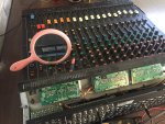
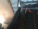
I went and took the P204 connector off the the BUS AMP PCB ASSY and hooked it to P405. Meter 4/8 was working with the tone with P204 hooked as it was supposed to, but when I hooked meter 4/8 to P405, meter 4/8 did nothing. So I was thinking it might be the board, but wanted to be sure, so I tried this setup

File Jan 05, 5 07 22 PM.jpeg

File Jan 05, 5 08 31 PM.jpeg
(if I woulda been thinking, I'd a used the Budweiser mirror.......)

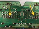
I ended up jumpering the R IN and L IN (where the yellow arrows are in the pic on the above post)of the 3/7. 4/8 Meter PCB to the R IN and L IN of the L/R Meter PCB to see if I could get the meters to move. Nothing happened there either..... So what I came up with is a cluster of a contradiction ....
:cursing: .

I have the chip to put in the original board and the sockets came yesterday, so I'm thinking about replacing the part, testing, and putting the original board back in to see
what happens.......
 
Inject tone at J405 please with everything else hooked up regular (i.e. all your meters connected where they’re supposed to be connected). Do the L-R meters respond appropriately to a 1kHz -10dBV tone injected at J405?
 
Back
Top