You are using an out of date browser. It may not display this or other websites correctly.
You should upgrade or use an alternative browser.
You should upgrade or use an alternative browser.
Need help...replace two back-to-back polar caps with one bipolar?
- Thread starter sweetbeats
- Start date
sweetbeats
Reel deep thoughts...
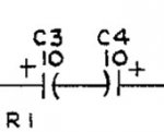
Wait...those are in series in the diagram right? So the equivalent bipolar cap would be 10uF right?
BUT...these caps are an input coupling cap so it couldn't hurt to increase the value anyway right?
BUT...these caps are an input coupling cap so it couldn't hurt to increase the value anyway right?
sweetbeats
Reel deep thoughts...
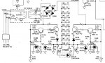
But...an input coupling cap...it wouldn't hurt to increase the value would it? 10uF or 22uF? I'm planning on putting a bipolar MUSE cap in there...below is a bit more of the view...that's an input coupling cap right? This is all line level. It is the input section of one of my CRL SEP400A's...multiband dynamics processor...
And am I understanding correctly that I can replace those two back-to-back caps with a single bipolar cap?
And am I understanding correctly that I can replace those two back-to-back caps with a single bipolar cap?
Attachments
sweetbeats
Reel deep thoughts...
sweetbeats
Reel deep thoughts...
Dang!
The guy is like a PHANTOM!
...glides out of the fog, says something brilliant and *poof* he's gone again!
The iron is hot...literally...I hadn't really checked out the schematic on that CRL unit in terms of prudent changes and I'm in the middle of pulling caps...
The guy is like a PHANTOM!
...glides out of the fog, says something brilliant and *poof* he's gone again!
The iron is hot...literally...I hadn't really checked out the schematic on that CRL unit in terms of prudent changes and I'm in the middle of pulling caps...
GCalo
Member
Capacitance in parallel doubles- in series 1/2's.
See: http://www.allaboutcircuits.com/vol_1/chpt_13/4.html
So a 5mfd at 16V non-polar (bipolar) should work.
You can by-pass all the large lytics with a .01 film.
Do it on the foil side after you pass the cap through, and solder all at one time.
See: http://www.allaboutcircuits.com/vol_1/chpt_13/4.html
So a 5mfd at 16V non-polar (bipolar) should work.
You can by-pass all the large lytics with a .01 film.
Do it on the foil side after you pass the cap through, and solder all at one time.
sweetbeats
Reel deep thoughts...
Okay...right...so as far as the circuit is concerned, a single non-polar 5uF cap is going appear the same as two back-to-back 10uF polar caps.
BUT...
I don't have any 5uF non-polar caps...would 10uF be okay or even desirable? 22uF? its an input coupling cap and I thought that going bigger might be an advantage. Its interesting...outside of the PSU filter caps, all the electrolytic caps are 10uF/16V...and outside of the input coupling caps there are NO electrolytic coupling caps in the entire circuit.
Must know...must finish it...must not let IT sit unfinished...
And, Greg, so putting something like a good quality 0.1uF metal film cap in parallel with each of the 470uF and 1000uF caps couldn't hurt right?
sweetbeats
Reel deep thoughts...
I have these for bypass caps:
http://www.mouser.com/Search/ProductDetail.aspx?R=BQ014E0104K--virtualkey58110000virtualkey581-BQ014E0104K
Will they work?
Still wondering if I should keep the value of the input coupling cap(s) at about 5uF or can I go with 10uF or would higher be even "better"?
http://www.mouser.com/Search/ProductDetail.aspx?R=BQ014E0104K--virtualkey58110000virtualkey581-BQ014E0104K
Will they work?
Still wondering if I should keep the value of the input coupling cap(s) at about 5uF or can I go with 10uF or would higher be even "better"?
GCalo
Member
This might be better:
http://www.mouser.com/ProductDetail...EpiMZZMvCt%2bwg%2braTuoTvd5PT1YKFYdph9INmQ/8=
Stick w/4.7 - 5.0.
http://www.mouser.com/ProductDetail...EpiMZZMvCt%2bwg%2braTuoTvd5PT1YKFYdph9INmQ/8=
Stick w/4.7 - 5.0.
LDS
New member
C33 and C36 should be your main filter caps. The 1000uF caps are for the plus and minus 15 volt supply sections.Have a look at the PSU section...
I want to try bypassing the filter caps with a .01uF film cap...but...are both polar caps on each rail filter caps? Bypass both? Or just the 1000uF?
sweetbeats
Reel deep thoughts...
Ahhhh...THAT makes sense.
So the 1000uF caps are like a secondary filter cap?
Nothing wrong with bypassing all of them?
So the 1000uF caps are like a secondary filter cap?
Nothing wrong with bypassing all of them?