MCI JH-110 Project

towble

New member
I recently bought an MCI JH-110 from a studio in a city near me. The unit was not from that studio, just being stored there. The owner claimed that it was working, but I had no proof, even when I bought it. I didn't even take the time to fire it up at all. I just bought it loaded it into my friend's truck and drove it home in a snow storm.

I've been working on it for about a month now, so I have some catching up to do I suppose. But I would like to post about it here just in case some folks would like to see the work I'm doing. Also to get help when I need it and I will need it! I'm not nearly as smart as I like to think I am! :p

More to come when I get home from work!
 
Cool! Looking forward to it. And you're gonna be extra busy when the Mystery machine arrives.
 
As I said above, I chose the worst possible day to go pick this machine up. An hour before I left town, it started to snow. A wet heavy snow that covered the highway in slippery slush. I do not drive myself, so I relied upon the help of a friend from work. This was not the first time I convinced him to drive me some distance to pick up a heavy object! Nor was it the first time the weather was inclement on the day we decided to go!

Anyway, I got the machine home safe and sound. I removed the power supply to make it a little easier to carry up the stairs at the studio and down the stairs to my basement. I also wrapped it in plastic and covered it with a tarp to keep the snow and rain off of it.

Funny story, we happened to be in a shady neighborhood in the city and while I was up in the box of the truck a man who appeared to be both mentally handicapped as well as slightly intoxicated attempted to sell me an iPod dock. You should've seen the look of confusion and exasperation on his face when I explained to him that I had just spent all my money on a tape recorder! :p

Anyway, I'll stop rambling and post a pic!


You can see that she's got some battle scars! I guess they didn't have splicing blocks back in 1977! :p

The empty reel was included as well as two flanges, ironically...a splicing block, a remote, a manual, an LED annunciation board, and one VIF and one Ampex NAB adapter. I like them to match, so I bought a NOS set of VIF adapters.

I didn't actually dive right in as usual. I waited a whole day before doing any work on the machine!

More to come in a bit!
 
Cool! Looking forward to it. And you're gonna be extra busy when the Mystery machine arrives.

Indeed I will be! That is, if it's a tape deck. If it's a mixing board, I won't feel too inclined to do anything with it for some time.
 
The day after I got the MCI, I started with the first step, cleaning.

The regulators in the PSU are accessible by removing a small panel from the front of the power supply. There are four of them for the main supply voltages: -15/+15/-24/+24. These four rails have test points beside their respective regulators. There are other voltages listed on the schematic though. +8 and +30 volts that are not regulated. There is also a 24VAC rail.

When I removed the cover from the regulators, I could see that the power supply was very dirty inside.


That's likely 40 years worth of dust! I took it all apart and cleaned it with the air compressor.

Also housed in the power supply in a module attached to the fan is the driver for the reel motors. They are DC motors. In that module is a board with two 741 op amps as well as various other components and two heat sinks that hold three 2N3055 power transistors. Both this section and the regulator access panel are held in with fancy little twist locks that I like very much!

After I had cleaned the PSU, I put it back together and set it up on the test bench to test the voltages. The four main rails were all within about 1.5 volts of their proper voltage. The -24 volt rail being -22.8 and the +24 volt rail being +23.2. The other two were about .3 volts off. I figured that these were good enough. Nothing was so high as to cause damage.

However, the +8 volt rail stands at around +14.1 and the +30 volt rail at +37.2. These are the two unregulated rails and the voltage measurements do not change much under load. None of the rails have adjustments. I've tested all the components and they are in spec. If these supplies are a little high, I guess that's what MCI wanted? I'll have to test them again under load just to see if I made a mistake before.

Regardless, I tested the machine at first using a piece of paper in the tape sensor. I tried various functions and everything was erratic. The counter worked, although the numbers it displayed made no sense. Dirty connectors. I tried the remote and got the same results.

The "Manual Velocity Control" (MVC) or as most people call it, a shuttle control, worked a little. It would sometimes lock in and sometimes not. Normally it locks in when one of the fast wind modes is selected first. Edit worked. Well at least it made some crazy things happen. The tape lifters did not work. The entire play function did not work. I was upset...but not for too long.

I had heard that these machines were infamous for bad connectors and IC sockets. I pulled the logic board out and put it back in and viola! It worked...kind of.


All functions work right aside from the edit function and counter. I get no response from the edit button. Also, the counter only works on 15 IPS and never displays the same information twice!!! It is built from three boards stacked on top of each other with loads of those bad connectors and bad IC sockets! But the return to zero function and zeroing function work.

The machine has three speeds, 7.5/15/30, all work.

I had to take apart the lifter and pinch roller linkages to clean and re-lube them. The old oil had become very sticky like molasses! Like an old Teac! :p


I also soon found that the cylinders that I imagine originally held up the transport did not do much of anything at all! I have to use a piece of wood with some V notches cut at each end to hold up the transport while I work under it!

I suppose this project will be done when I lose a hand to this machine! :rolleyes:


You can see another started and put on hold project on the workbench behind the MCI. It's a Studer B67.

More to come later tonight! I'm not very fast at composing my posts! I'm also long winded! :o
 
Okay, continuing on.

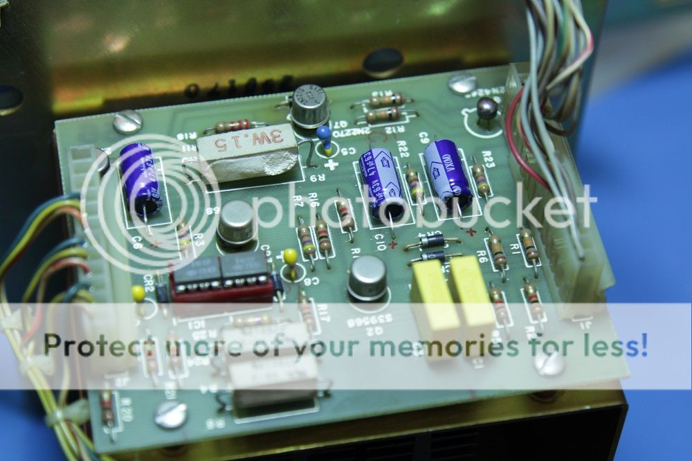
After I got the machine running, I knew there were a few things that would have to be done. There are 17 capacitors in the power supply, 15 of which are electrolytic, 4 of which are tantalum. I replaced all 50uf caps with new 47uf caps. Six of those were aluminium electrolytics that looked rather crusty and the other was a tantalum that I thought I'd just replace for the hell of it.

I also replaced the two caps that were not electrolytics with safety caps, again, just because I can. That leaves the five 8700uf main filter caps and three small tantalums on the motor driver board. Two .47uf and one .68uf.


I ordered this nifty little ESR meter kit from Altronics: K2574 - Silicon Chip Magazine ESR Meter Kit - Altronics Why a kit? Well it is cheaper than one that's already built. This one also seems to be bulkier and better quality than a lot of other ones. And I love soldering, so why not?! Kits are fun! :D

Anyway, once I have built the kit, I will use it to test mostly tantalum caps throughout the deck. I'm going to assume that most if not all aluminium electrolytics are bad and replace them. Although the 8700uf filter caps in the power supply seem to be doing fine. I checked the supply ripple of the 24 volt supply yesterday and it looked pretty good. I'll check the rest eventually and I may just replace them anyway...

This is embarrassing... Um, I didn't have any...any tape...:o Like none! None at all, I had not a single reel of tape. Not even a puny 3" reel... You see, I once sort of gave up on magnetic tape. I just had so many hobbies and tried so many different things looking for fulfillment. One day I just decided I had too much stuff and everything tape related was parted out to people I knew who were interested in such things. I hadn't done anything tape related in about two years, then I got the B67 from my uncle and that interest was sparked up again. Hopefully I'll get more out of it this time.

I have moved since then. I now have much more space to work and to store stuff. I think things will go well!

Anyway, I digress. I bought a reel of tape online. I wasn't worried about whether or not it was good tape. I just needed something to test the transport. This machine uses dynamic braking. " :wtf: is that?! " I thought. I had heard the term before and I knew what it meant, but I didn't even know that there were recorders that used that! All the other recorders I ever had used AC motors. Now I have this beast that uses DC motors with tachometers! This machine is probably smarter than I am! :p

Without tape, I wasn't sure that the machine was working correctly. In fact, I guess I'm still not sure. Without tape, in the fast wind modes, whatever reel is the take up reel at that moment seems to have little if any braking behind it. It seems to me that the inertia is being put through the tape to the supply reel. The supply reel seems to be doing all the braking. I was worried and I still am worried that the tape has too much tension on it when braking from the fast wind modes. I have never worked with dynamic braking in a tape machine. I'm really clueless. :confused:

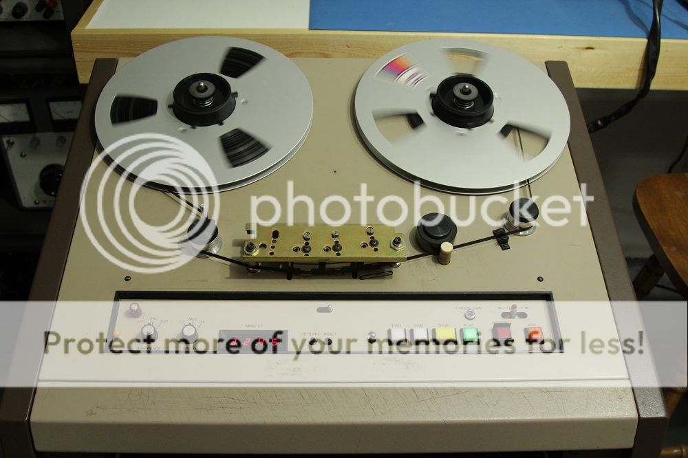
Her's a pic of the machine with tape on it:


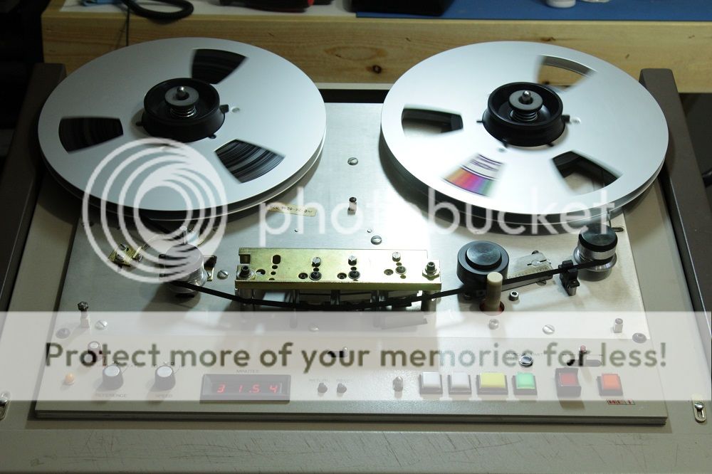
I had to give all the guides, heads, rollers, etc. a good cleaning before running tape through it. A lot of bad tape was put through this machine at some point. It took ten minutes to clean each head and the erase head still doesn't look clean. Even some of the guides had to be scrapped to get all the crud off! But it sure is shiny now!

The heads are glass heads? There's a technician's notes in the manual describing slightly pitted glass heads. These ones look like glass and they are slightly pitted. Here's a pic of the heads:


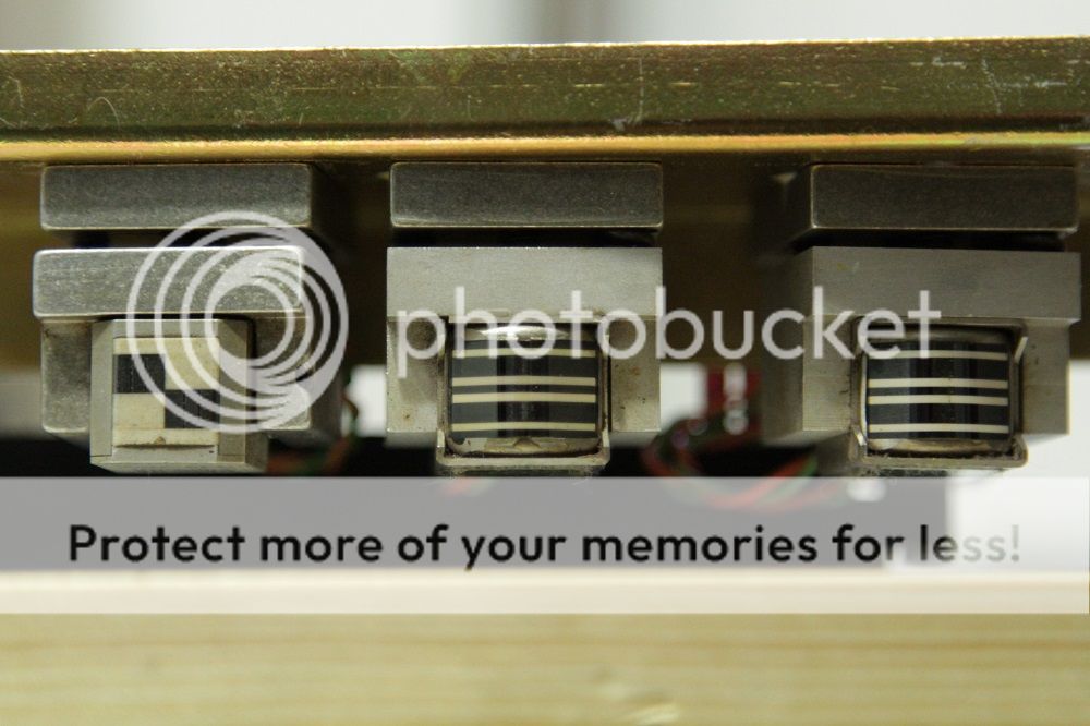
I forgot to clean them before taking the pic... And here's a close up of the playback head:


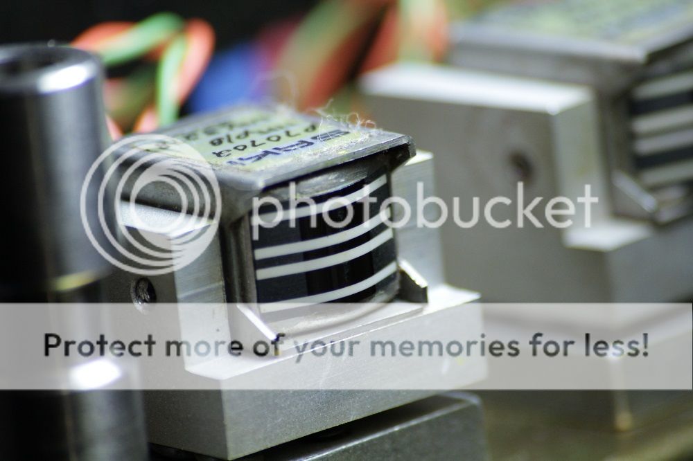
I really like the look of these heads! They're stylish!

The JH-110A can be up to four tracks. This one is set up for two, but the PCB connector that the head block plugs into still had the four sets of cables. One for each potential track. That was good since I noticed some damage to one of the cables that was used and replaced it with one of the spares. I removed the other spare just to keep things neat. I only need two channels anyway.

Here's what the transport looks like right now with the dress panel back in place:


I am missing one screw for that panel. The yellow light at the far left is an addition that someone made. It comes on when the reference for the capstan speed is in any position other than fixed. Not a bad idea when making a recording I suppose.

The shield for the playback head is manually controlled by the leaver in front of it next to the fast rewind button. The other lever up and to the left of that is a manual control that moves the lifters to pull the tape away from the heads at any moment. It does not work in reverse though.

Well that's my 10,000 words for today! I hope someone enjoys that! :p
 
The power supply is currently still in pieces as I am still working on replacing some parts. The cooling fan did not work very well when I got the unit. It was a 12cm 115v brushless fan and would only spin when I gave it a nudge. I tried lubing the bearings and it made no difference. Not a big deal, they're pretty cheap so I just went ahead and bought a new one.

Of course, the air flow on the new one is opposite, so I will have to mount it backwards and put a filter on the front of it to cover the open side. That should also limit the amount of dust that ends up inside the power supply.

Right now I'm just waiting on new rubber grommets. The old ones were rock hard and broke apart. Once I have those, I can install the new fan and do some more tests on the power supply.

Here is a pic of what it looks like taken apart:


Pretty generic linear power supply.

Here's a close up of the "wind tunnel" as I like to call it, where the motor control transistors and heat sinks sit:


The control board mounts on the screws on the side, and the fan mounts through the grommets on the back plate and into the "wind tunnel". That way the whole motor control unit can be removed for servicing without taking the power supply apart. I'll be sure to take a pic of that when it's back together. I think that it's a neat design!
 
I ordered replacements for the 8700uf power supply filter caps. I actually ordered 4700uf caps and will use two of those to replace each 8700uf original. The old 8700uf caps were -10/+75%!!! So roughly 9400uf will not hurt anything.

I will be mounting the new caps either on single sided copper clad board that I will drill and etch by hand, or single pad prototyping board that I will hand wire. I have done similar simple etching with a dremel tool cut off wheel. It's just straight lines anyway. It's turned out well in the past.

Here is a sort of half schematic/half layout diagram:


Now we wait for parts... I hate waiting for parts. :yawn:
 
Interesting stuff. Are you planning to feed it RMG or ATR tape when it's up to spec?

Some people swear by RMGI and others by ATR. To be honest, I have no experience recording on modern tape. All the tape that I have ever used, which is not much anyway, has been old tape that was used and reused and reused. I suppose when the time comes around, I'll have to get some new formulas and play around with them to compare.

The JH-110 can be switched between CCIR and NAB via push buttons on the record and replay cards. I will likely record exclusively on 15IPS and think that it would be worth while to try out CCIR since it should have lower noise than NAB at 15IPS.

I'm not looking for the best record and replay quality in the end. I don't run a studio or anything. I'll likely just record some music from MP3 files and play it back on occasion just for the hell of it.
 
What a beast! I'd say you're off to a fine start getting the old girl up and running :)

Thanks! I hate sitting idly by waiting for parts. It'll be a few weeks before the PSU is done.

I have no experience with MCI machines and I hear they can be quite fickle! Hopefully she will perform top notch once I'm done! I don't look forward to cleaning all those connectors!
 
The biggest issue with those MCI s are as you have discovered, the shitty connectors used in them.

One of my far past jobs was Maintaining a studio that had four of them, 2 24 track and 2 2 track. Never ending connector issues. Also the sync system to tie the 24s together was hell on my temperament.

Yeah, I plan to go through and clean all the connectors. I'm also going to replace the red IC sockets.
 
Show of hands, how many people thought I had given up?! :p

In reality, I haven't touched the machine other than the playful turning of reels for over a month. I have been waiting for parts that take forever to ship from China. But they're all here now and assembled into the new power supply filter section.

Here are some pics:


Everything works right. At least, we're at the same point we were before. But at least now I don't have to waste any time worrying about the filter caps drying up.

One thing seems different though, but I have a feeling I'm just not remembering right, the shuttle control seems slower at top speed than it was before. That and the counter doesn't count now. But that thing's always been a mess.

Anyway, that's where I'm at.
 
Took the counter apart today, cleaned the contacts and replaced the red IC sockets. Now the counter only counts odd numbers...
 
It was dirty contacts, I should've known! I cleaned all the contacts with Deoxit thoroughly and still have a lot of problems with the counter.

Unless someone has better advice as to how to clean the connectors so as not to have further problems, I'm seriously considering soldering it all together. It's not like I'll have to go into the counter boards very often anyway.
 
Another board done. This one was a lot of work.


I don't have the same connector issues with the other boards like I do in the counter.
 
I got even more done tonight by ripping myself off as far as sleep goes. I'll be lucky to get four hours before work tomorrow.

Anyway, all DIP sockets in the transport have been replaced except four on the logic board that look quite new. I even replaced the two eight pin sockets on the mother board that were a real pain.


While I was working on boards, I also replaced electrolytics and tested resistors. There is a modification on the capstan control board. A telephone wire jumper. Things seems to work right, so I left it in there.
 
I did a bit more work on the JH-110 today. I fixed some sloppy wiring on the transport and finally got around to the audio section. The good news, it works!!! At least, it plays fine. I didn't test the record.

I'll need to get some XLR cables, since I've never owned any! :o I'd also like to get some DI boxes. I'm not sure if I need them necessarily, but it would be good to have some anyway. The good ones with transformers in them.

The selector switch for the left channel is also broken. But I may be able to fix that. If not, it may be tough to get another.

It will be a while before I get parts though. There is supposed to be a postal strike here in Canada.

I'll post a short video once I gt it up on photobucket.
 
Back
Top