Richard,
I don't think I'll ever get over that pic of that studio you worked in...I'm sure you are completely aware of what that gear, in functional condition, would go for today. Love the 4-track 350 (?) on the right in the console. That's a beaut'.
And also, I can't get much by you huh? You knew it was some kind of 2" 16-track deal dintcha?

And Ghost, you were on the right track (no pun intended).

Muck, yes I
do have the 8 additional electronics modules.
")
They are coming from my 440-8 which, after acquiring the MM-1000, has had a pending status of "parts donor". I've been hanging on to all of the 440-8 just in case a good deal on a 16-track block came along...I've been in a holding pattern on what came via UPS yesterday because my friend who put the package together is very, very busy and it took digging through offsite storage to find the stuff, etc. I wasn't sure if the 16-track block was going to be part of the deal but now that it is here it is time to part out the 440-8. Bittersweet for sure, but it is hard to argue with the notion (in my mind) since I need a number of bits and chunks from the 440-8.
So, yes, I'm implying above that there was more to the package that came yesterday...
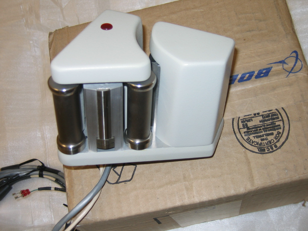
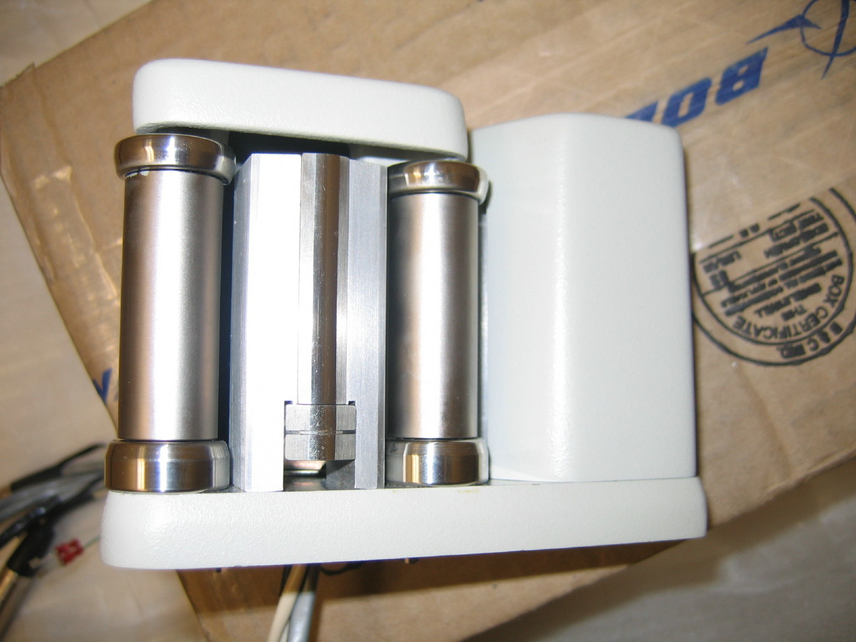
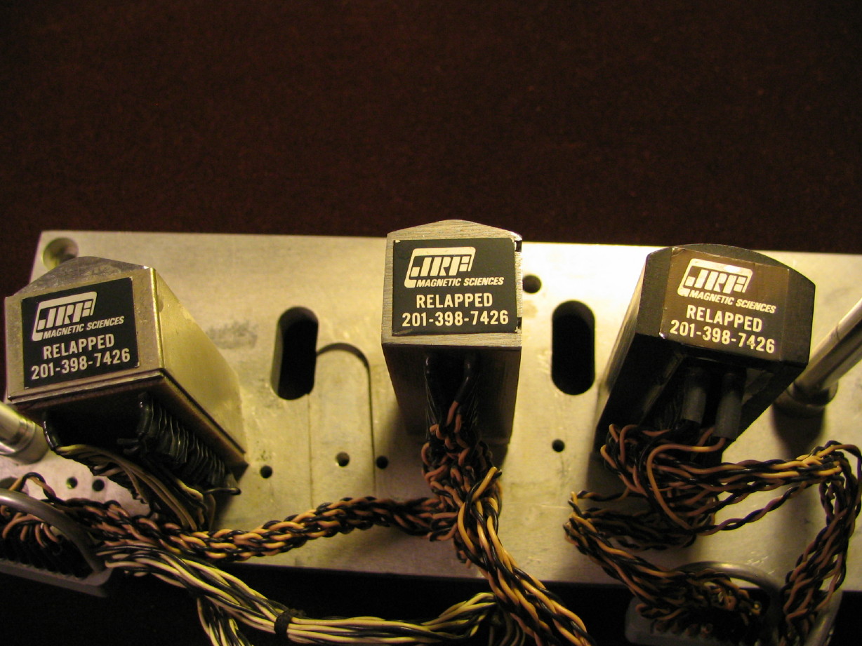
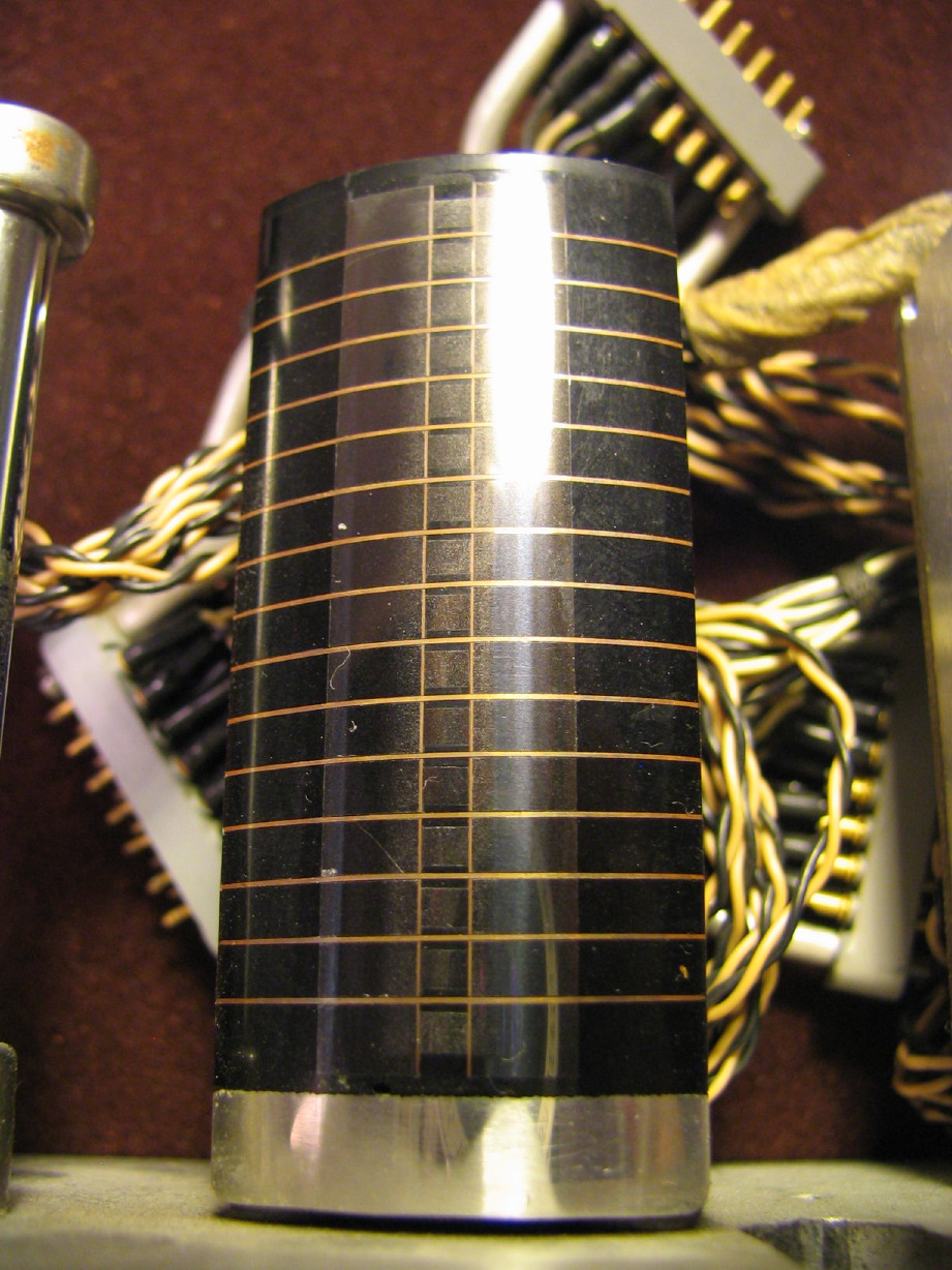
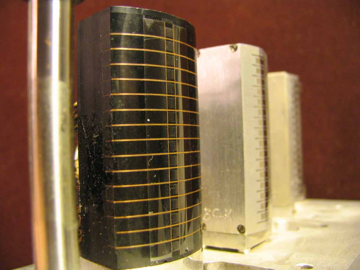
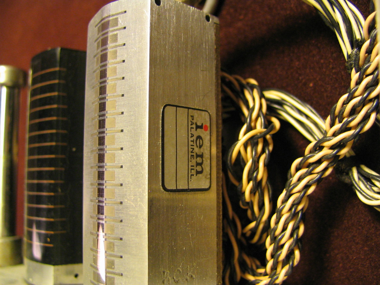
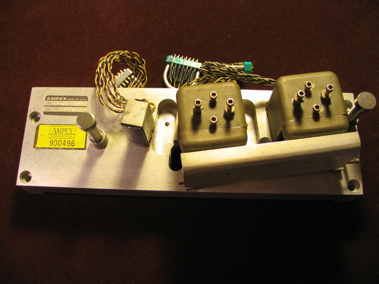
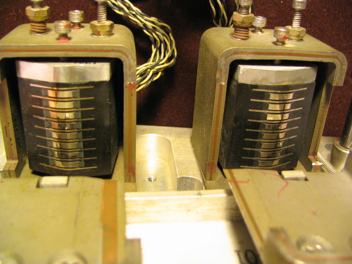
First off, more pics of and info about the 16-track block...the record and playback heads are IEM heads like I presently have loaded in the 8-track block that's on the MM-1000. Some people like them, some people don't in terms of their sound. I don't think I'll ever be in a position to complain. I think I'll like whatever goes onto and comes off of tape through those 440 electronics and wide-format heads regardless of IEM or Ampex branded. The heads on an MM-1x00 2" block are totally fixed except for wrap angle. This can be good and bad if the fixed zenith and azimuth aren't correct. Judging by the wear pattern I'm really impressed. There is a
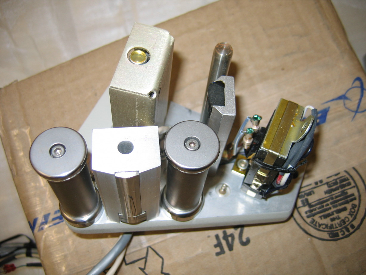
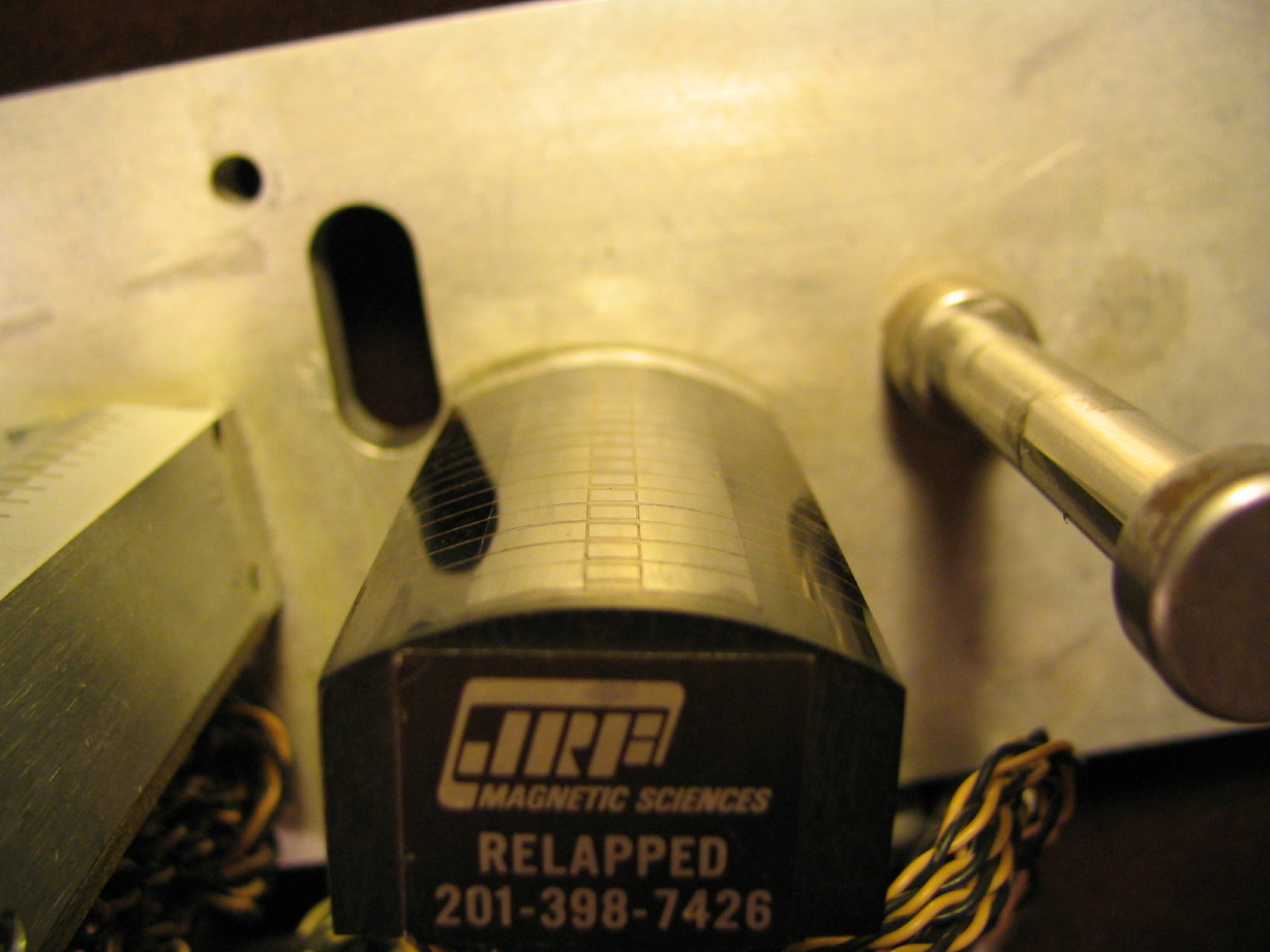
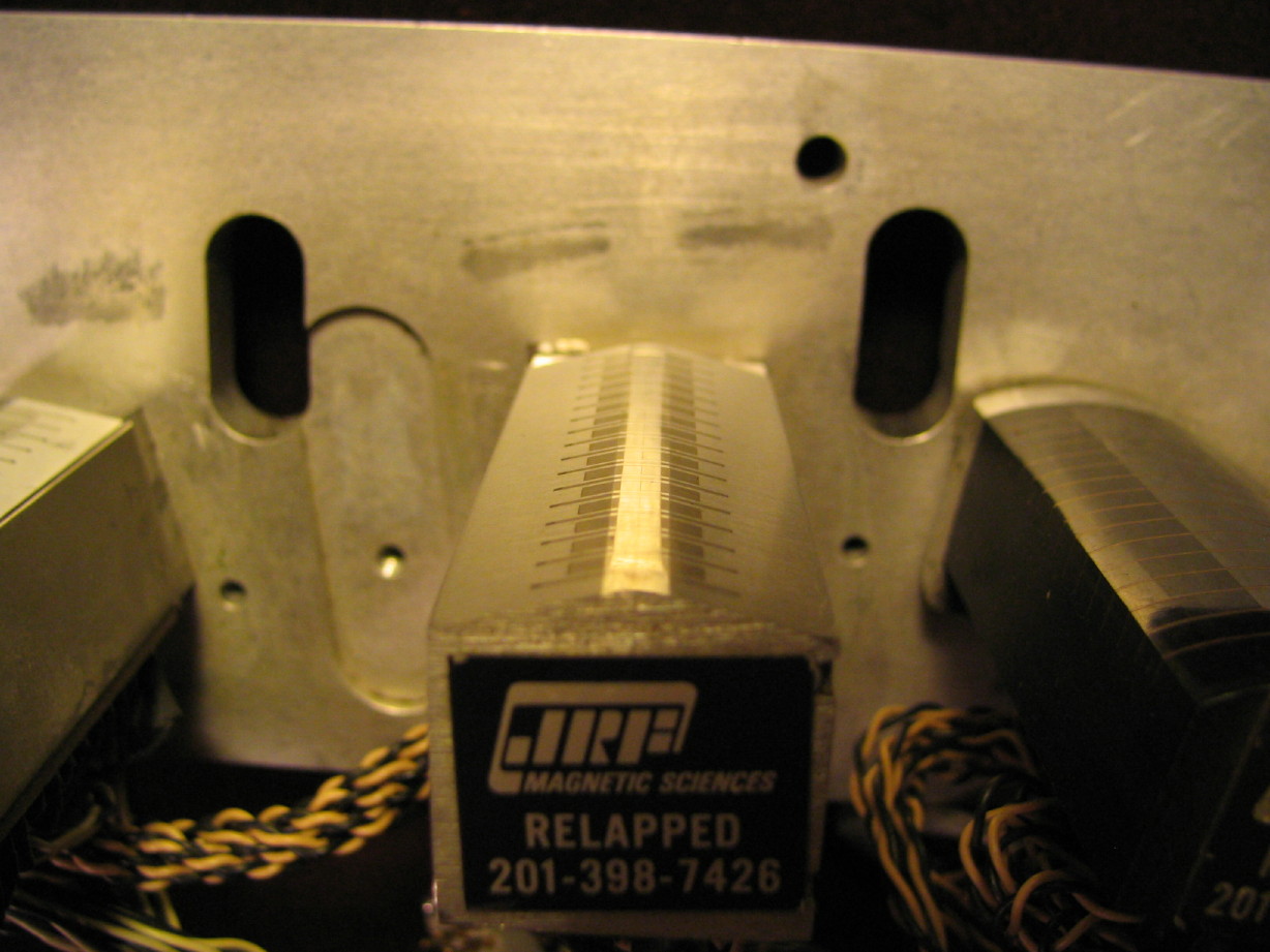
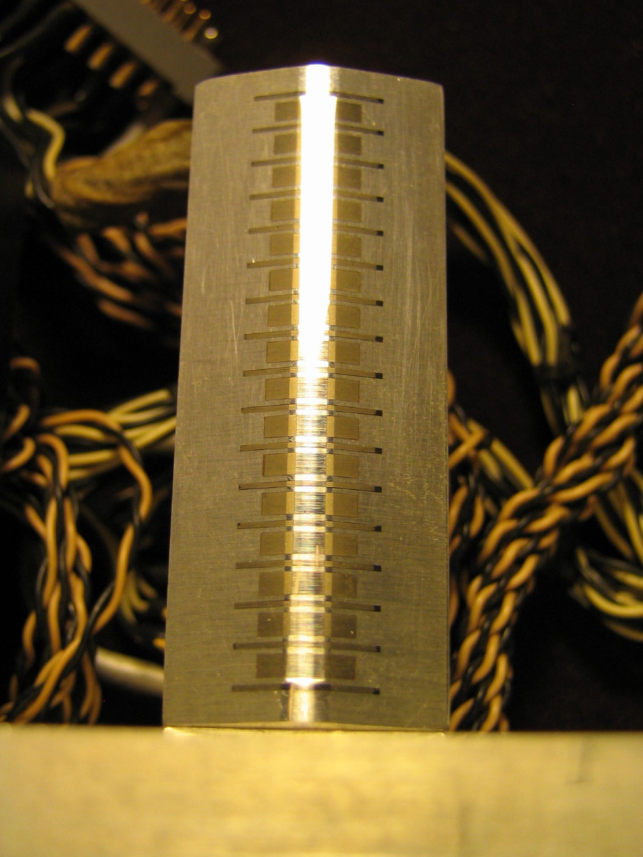
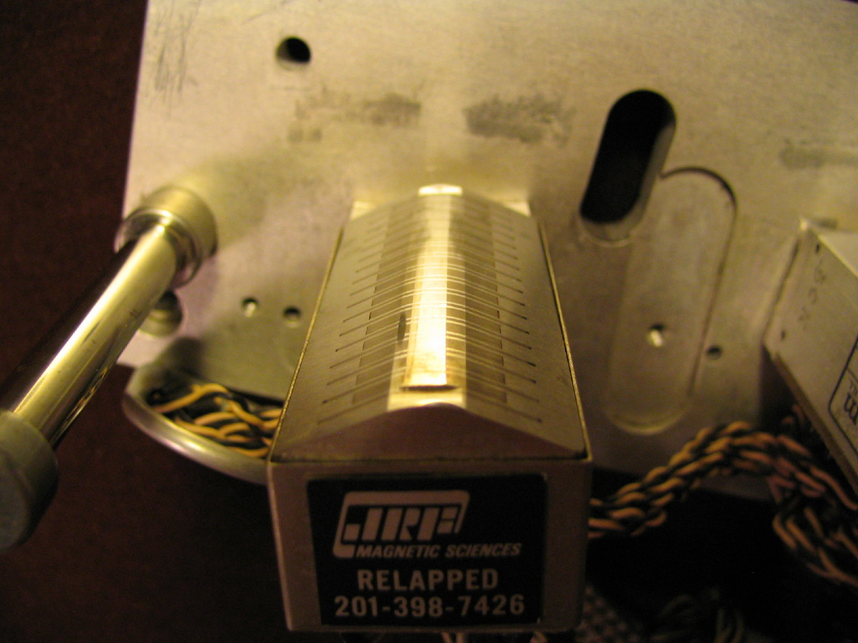
little bit of hourglass to the record and playback heads but its not much and I think that just comes with the territory...plus it is very even wear. This block has been relapped (and I assume setup) by JRF, but it honestly looks like much of the profile is still intact and the wear since the relap is pretty low...I think these heads have quite a bit of life in them. Looks like John French cut edge slots in the playback head which is nice. The erase head is just gorgeous. That's stock Ampex. There is a fragile solder joint on one of the wires going to track 16 on the playback head but that should be easy to repair. My friend was able to locate all the shield cans and gate hardware. The only thing that is missing is the scrape flutter idler that goes between the record and playback heads so I'm on the lookout for one of those.
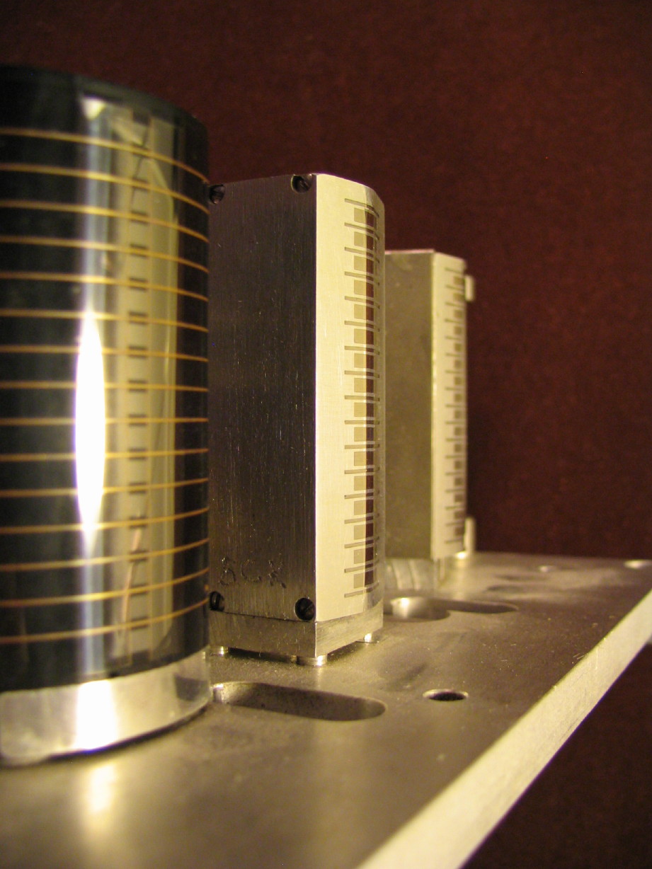
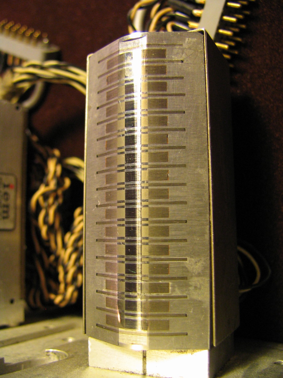
Erase Head:
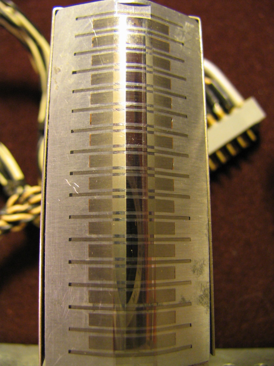
Record head:
Playback head:
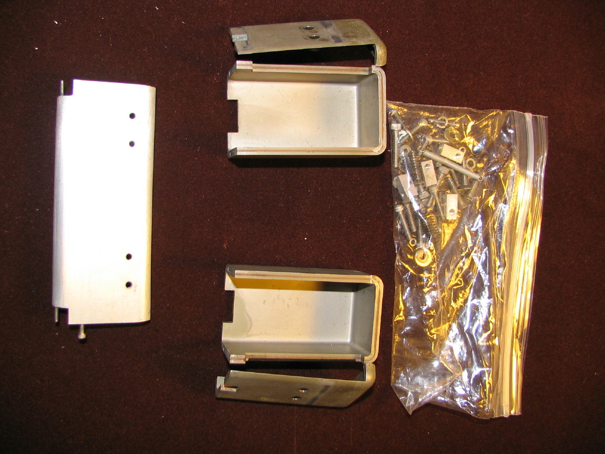
Additional block hardware:
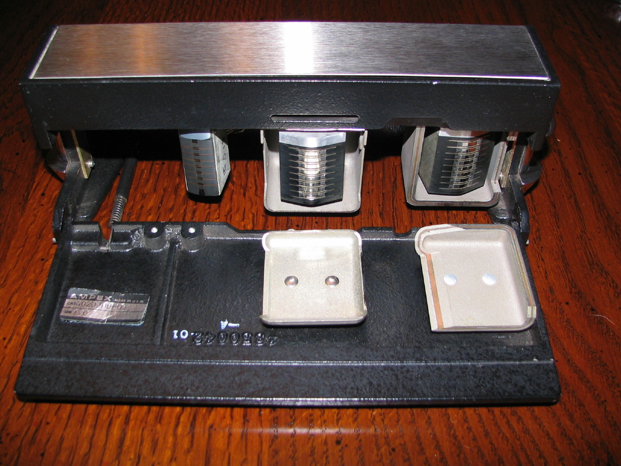
How about a complete (except for scrape flutter idlers) 8-track headblock assembly? The heads are so-so but the best part of this is that the block, gate, guides and shield cans are there. I have a set of basically new 440C-8 heads with the proper playback amp cards. The 'C' heads have a better response as they were constructed with thinner laminations. So I have the parts to have a spare block setup for 8-track operation.
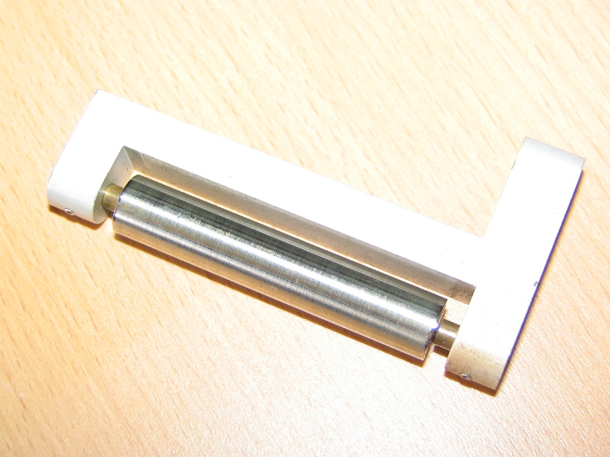
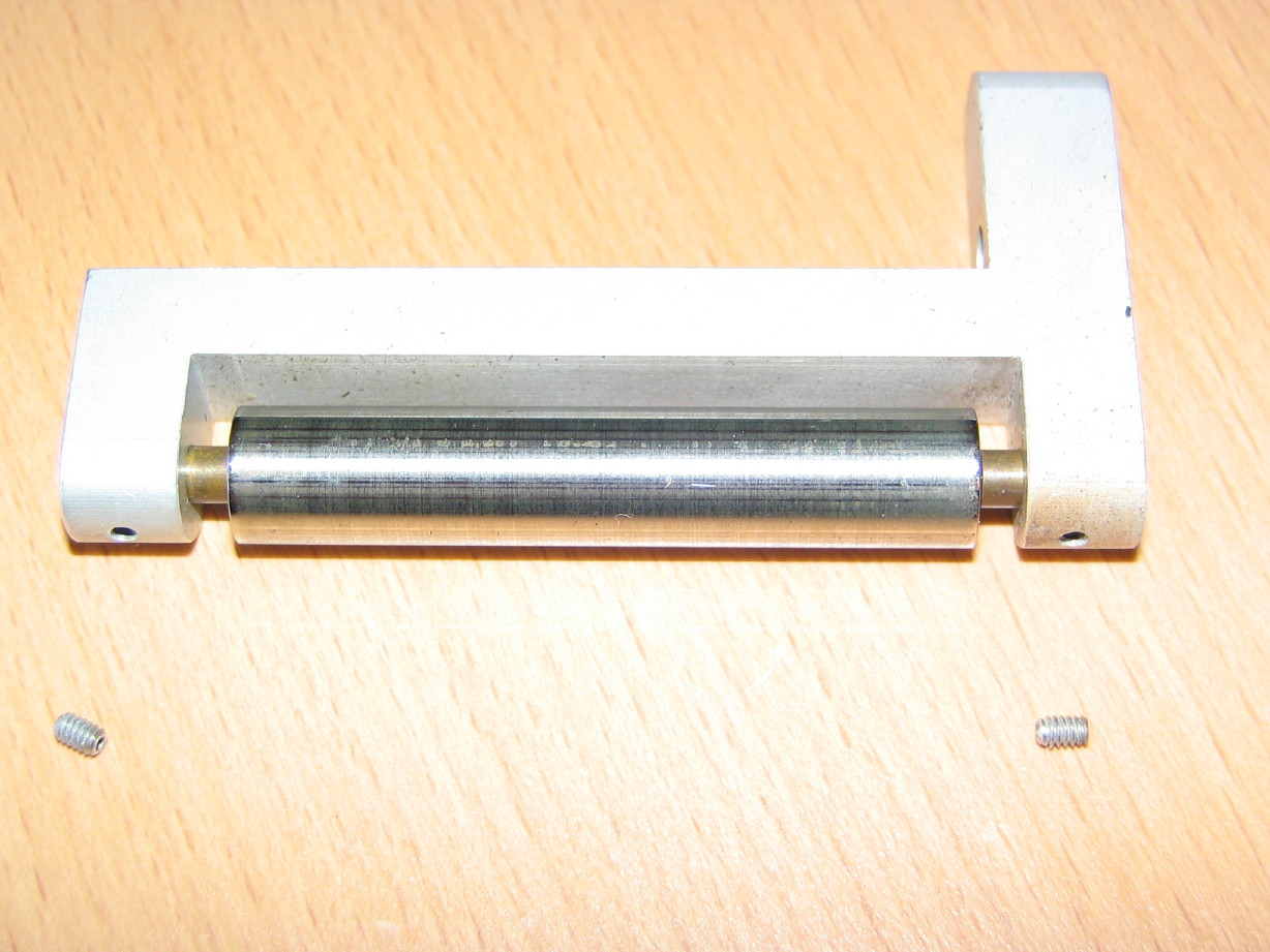
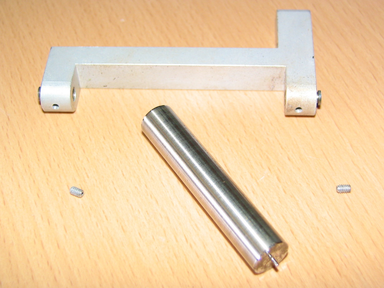
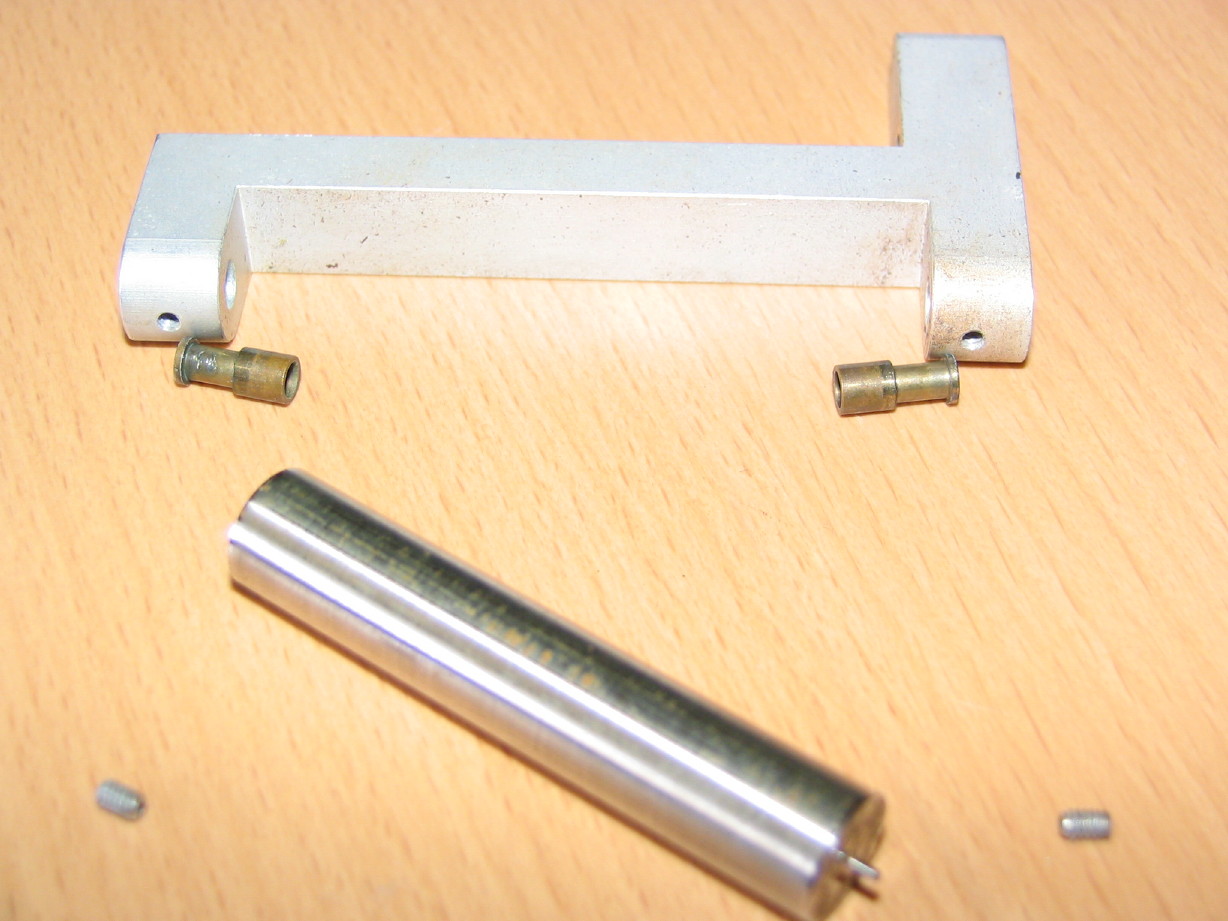
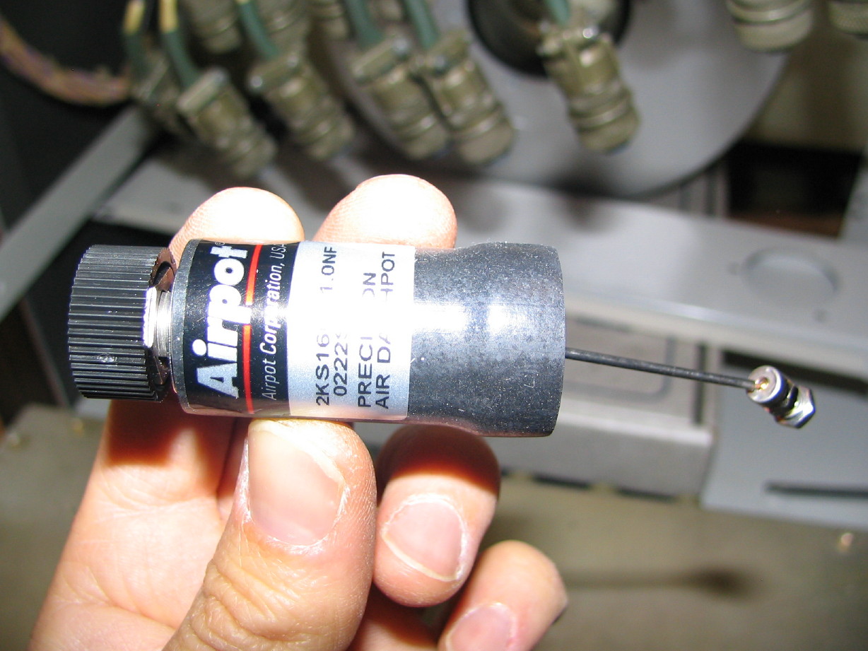
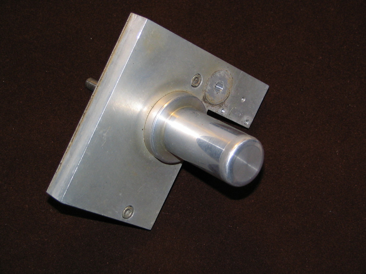
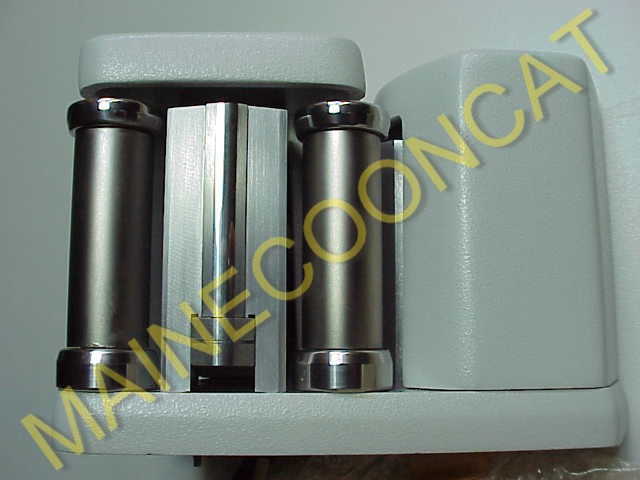
A reel idler roller...this is the roller for the critically important reel idler assembly with the viscious-damped flywheel. My MM-1000 presently has a roller for 1" operation as it has a shallow grooved section in it for 1" tape. This is the 2" part with the baseplate and bearing housing to boot. Its in good shape and is essential for converting to 2".
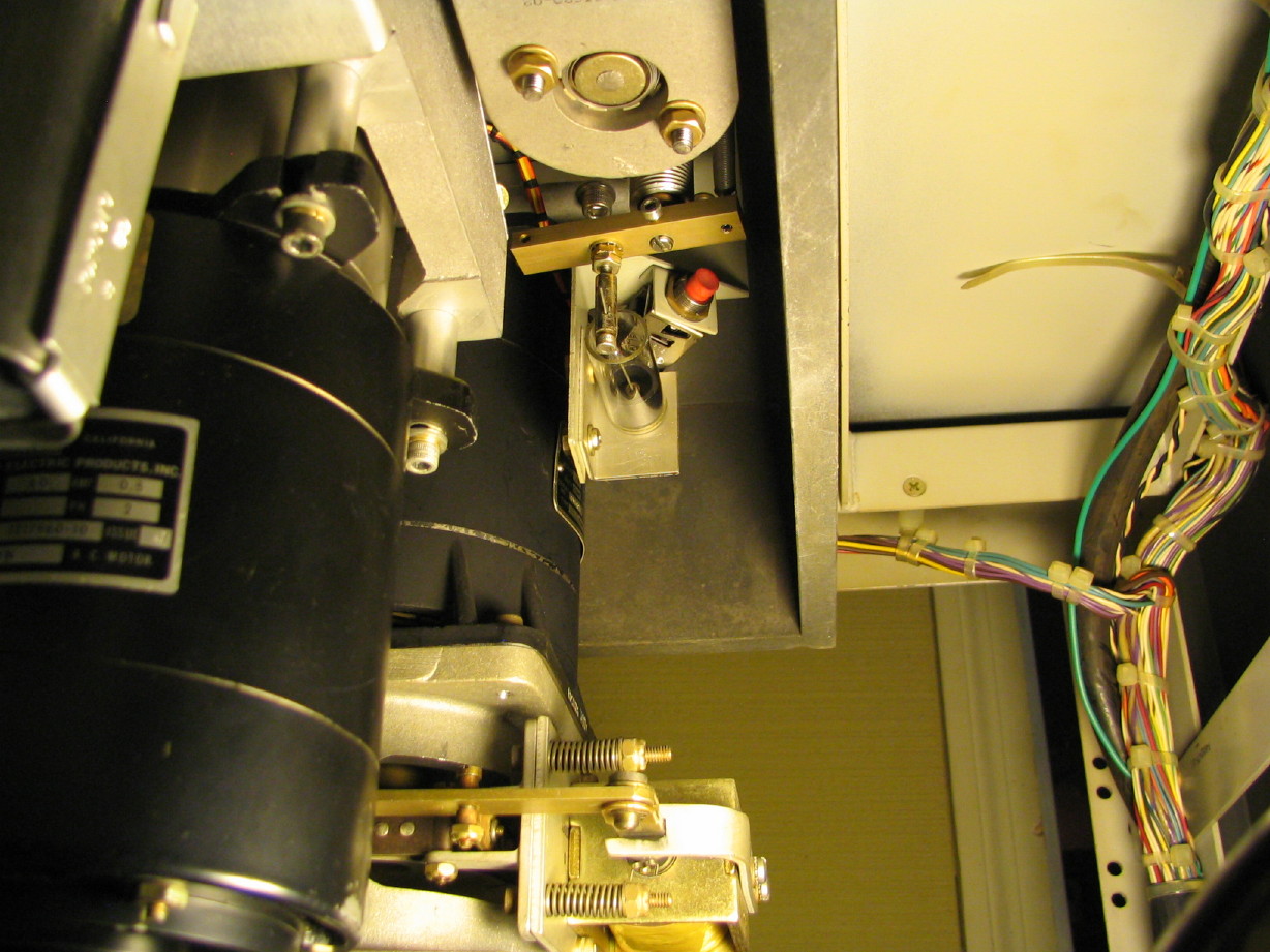
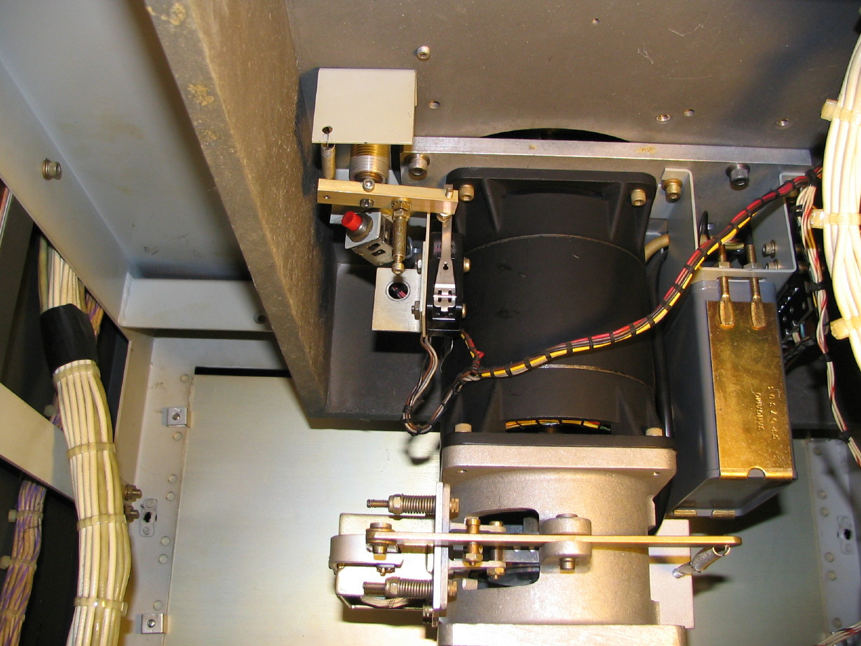
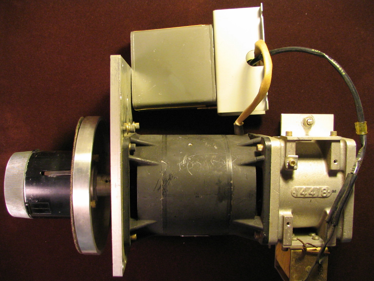
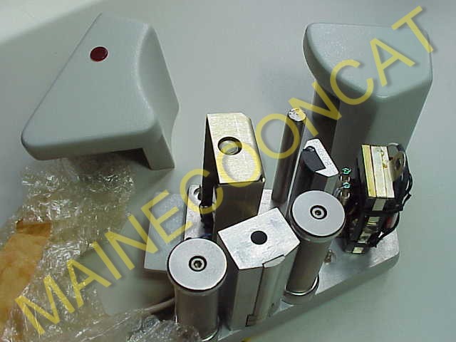
How about a complete reel motor assembly? Not that I'm really worried about the my motors ever wearing out...they are a brushless AC torque motor (so no brushes or commutator to wear out or dirty things up) and the bearings are relatively huge, but it is a nice peace of mind to have a spare motor
with a complete brake assembly, motor start capacitor and reel table/hold-down. Sweet!
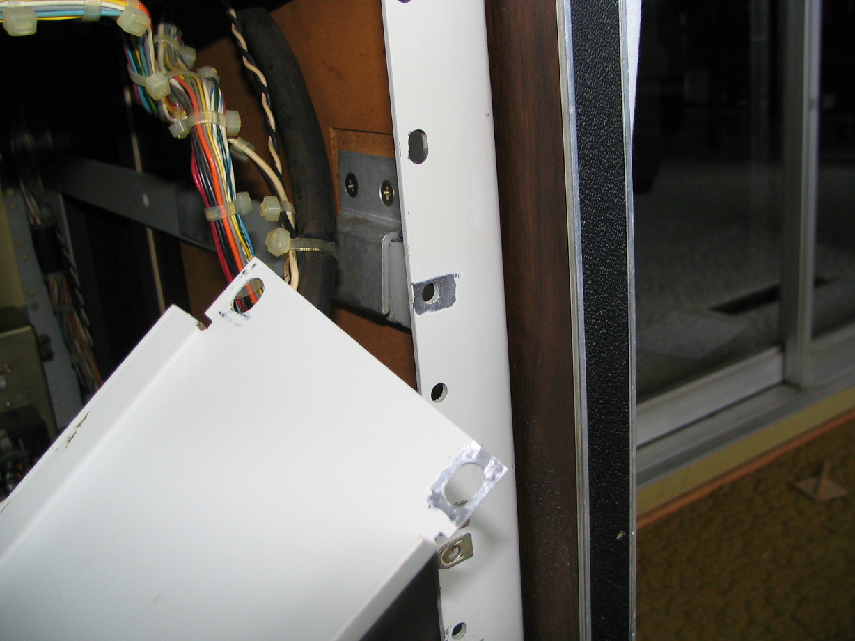
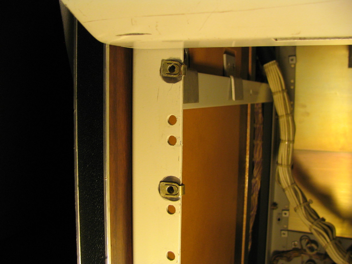
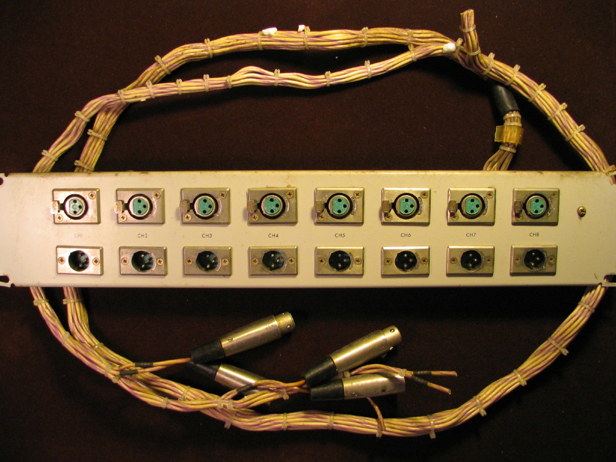
Here is an essential part for the conversion...an additional 8-channel I/O panel with cabling. It is in pretty good shape, just needs some cleaning up. The panel and cable harness are labeled for channels 1~8. Now, you know me...I wish I had the panel with the 9~16 labels but this is actually a good thing that this assembly is the channels 1~8 version because over half of the XLR jacks have been cut off...one whole 4-channel side of the harness has been hacked, but because it is a standard harness for the standard 8-track MM-1000 the cabling is long to go up to the overbridge. I'll need to get some XLR plugs but the cabling is long enough that it will be easy to modify to connect up to the 8 additional electronics modules that will be in the
lower section of the console.
Got some head cabling which will come in handy. This is one area that I'm still short though for the record head, but these assemblies are good to have on-hand.
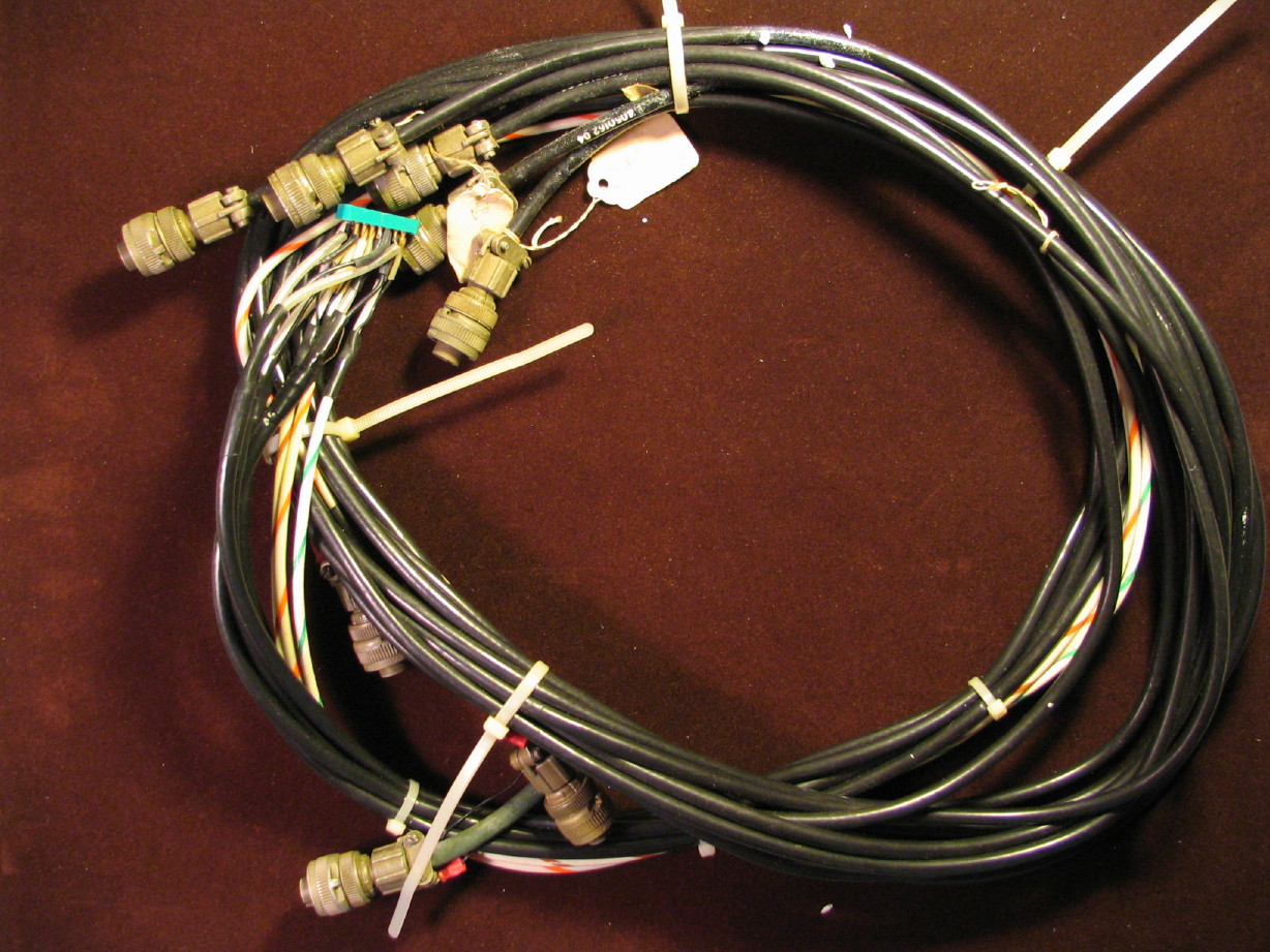
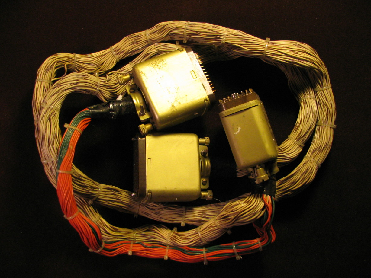
And then there's this bundle...I have no idea what this is...not even sure if it goes to the MM-1000 but my friend put it in the box. The 120-pin Winchester connectors are nice to have...

Hmmmm...I wonder if this was a Y-connector to hook up an 8-track remote and a 16-track remote to control a 24-track MM-1000...
And all this only cost me shipping!
Stuff I don't have yet but is either on the way or has been located and it is just a time or logistics to get it here:
2" rolling tape guides...2 are needed and I found them on a NOS VR-2000B quad video machine erase head block. Had to pay for this but got a good deal considering the cheapest I've seen for 2" rolling guides is $175
each...

Used typically go for around $125 each. Its enroute.
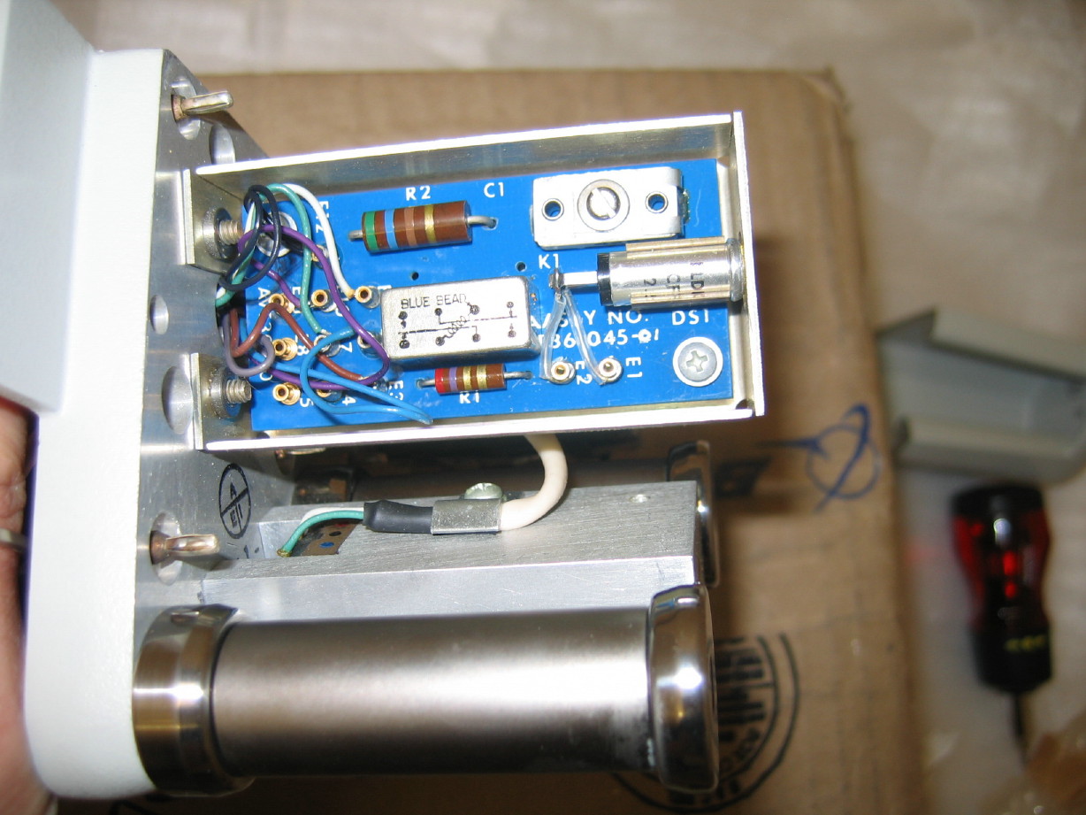
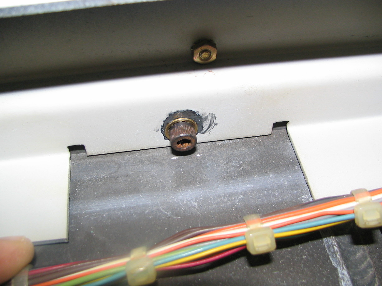
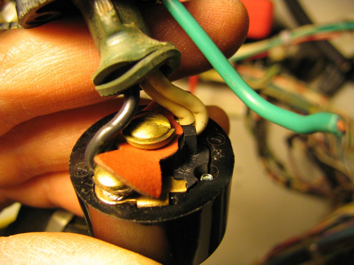
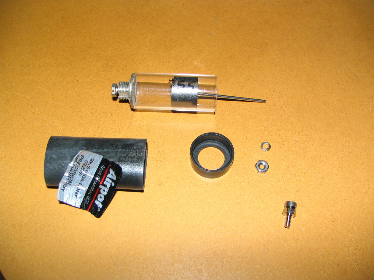
New motion sensing switch...you may have read above that one of mine is broken...functional but exposed (case is broken open) and a bit quirky. I've sourced one of these and it'll be here at some point.
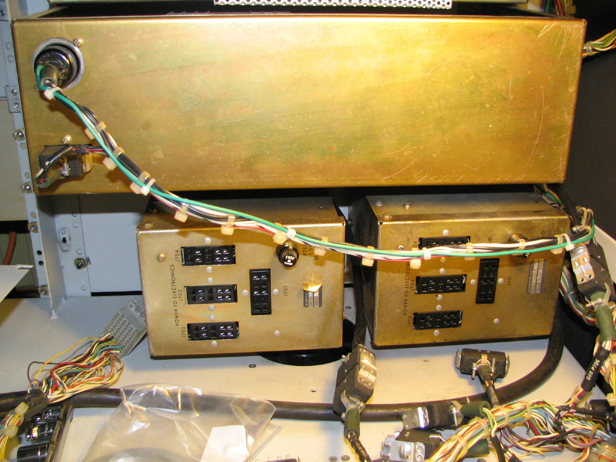
39V PSU mount panel...there is a rackmount panel that holds two 39V PSU's (each PSU powers 4 electronics modules). I need the panel. Much preferred over duct tape or zip ties...I have located one and it will be here at some point.
Another item that is not 2" conversion related but desired (and has been located and will be here at some point) is a cover for the Control Relay Box...right now all my big chunky control relays are exposed at the back of the MM-1000. There is a nice factory cover that goes over those. Not operationally necessary but there is quite a bit of line voltage running around in that box and I have 4 kids running around...
Stuff I'm still needing:
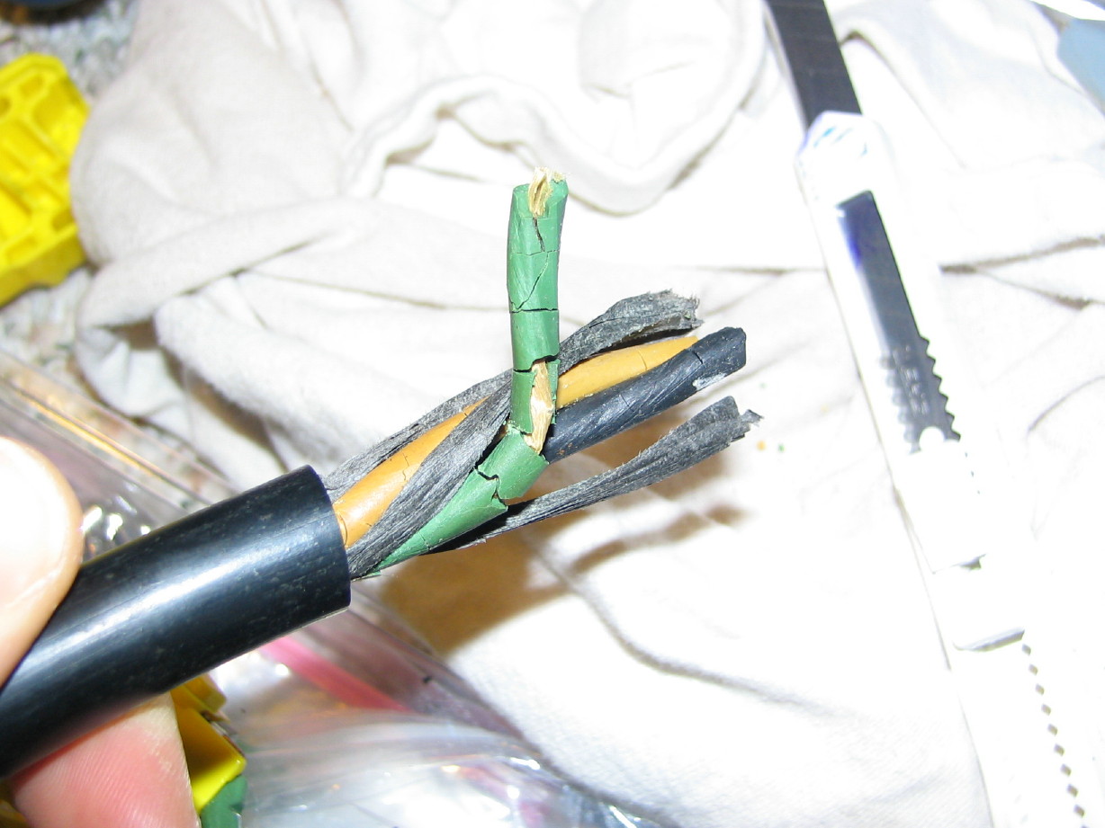
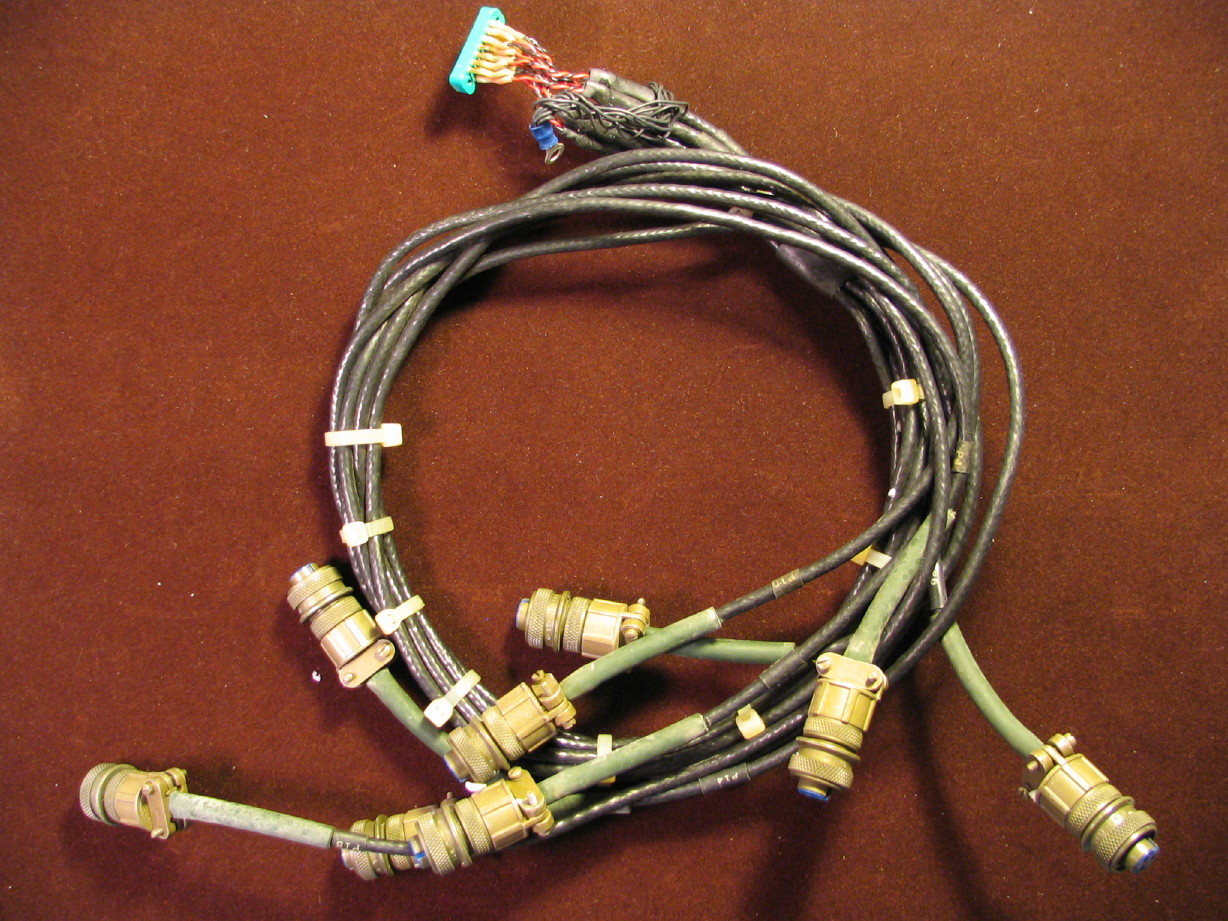
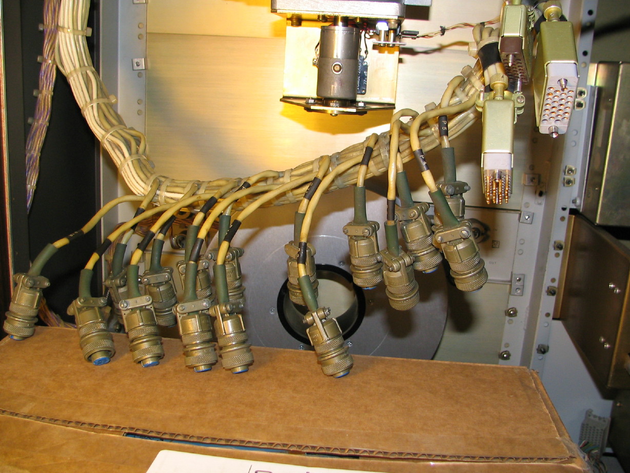
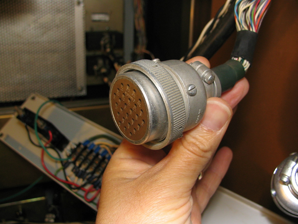
This mess of a harness...this is why I'm still in a pickle with the record head cabling because these 16 mil-spec connectors and the three Winchester connectors hook up to one of the 2 8-channel sync boxes needed for a 16-track MM-1000. I have a spare sync box, but only the one harness that's presently in the MM-1000. The harness is in between the electronics modules and the record head, going through the sync box, and also interfacing with the control panel. Pretty important and the mil-spec connectors aren't easy to find nor cheap:
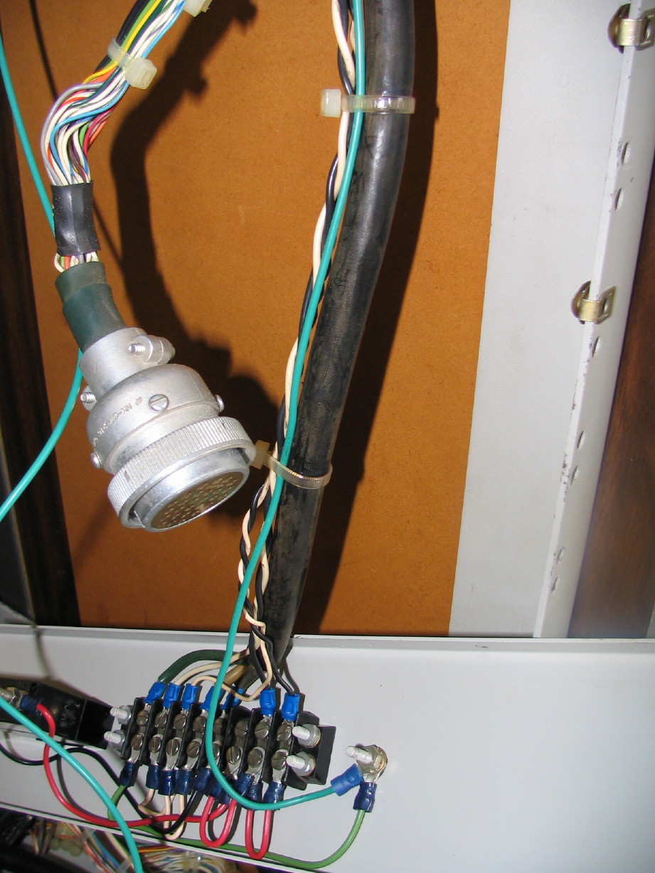
And I also need one of these Amphenol connectors and hopefully some cabling...this goes from the control panel to control the record arming and such on the electronics. The 8-track has one connector set, the 16-track has two and I'm lacking the second female connector for the 16-track...the mode control switch assembly has the male ends and I'm swimming in mode control assemblies but I gots no connector and wiring for the other side...
And lastly, the above mentioned 2" scrape flutter idler for the 2" headblock.
Once I have/track down the stuff above my MM-1000 will be pretty much complete and capable of running in 1" or 2" trim, and I'll have a healthy portion of spares.
Converting an MM-1000 from 1" 8-track to 2" 16-track is not for the faint of heart if you don't already have the parts on-hand...I suppose that would be the case for any conversion of the sort, but to do it you need:
- 8 electronics modules
- 2 additional 39V PSU's with mounting panel and wiring harness
- 1 additional sync box and wiring harness
- 16-track mode control switch assembly and wiring harness
- 16-track control panel dress panel
- 1 additional 8-channel I/O panel and wiring harness
- 1 additional 8-channel erase head connector harness
- 1 additional 8-channel playback head connector harness
- the 2" headblock replete with shield cans, gate, guides, scrape flutter idler and...oh yeah...heads

- 2" reel idler roller
- 2 2" rolling guides
I think that's it.
This is all assuming you already have the console with the overbridge to fit the electronics as well, unless you mount them in an outboard rack and then you need to make sure the interface cabling to the heads will reach.
Phew!
Trust me...if you want the 16-track version just look for a 16-track. The only reason I'm doing this is because I already had the majority of the stuff to convert and my friend offered up most of the remaining (and critical) components.
I will likely focus mostly on running the MM-1000 in 1" trim just for the economy of it, and this conversion project won't be happening for awhile anyway. Its just that doors are opening at the moment for the gathering process.

") https://homerecording.com/bbs/showpost.php?p=3384809&postcount=194
https://homerecording.com/bbs/showpost.php?p=3384809&postcount=194