This is the lamp you want:
8V 100mA Axial Lamp 0.16" x 0.8"
They are the solder in type. They also come in 6 and 12 volt for the same price. You may want to get a 6V to try but I'm pretty sure they are the 8V. The lamp circuit is 6V and Teac was pretty consistent, at least with the meter lamps I have experienced, at using 8V lamps in parallel pairs with a 6VDC power rail, or 8V lamps in series an 11VAC power rail. I'm certain they are not the 12V version.
If you want to do LED's you'll likely need to put a current limiting resistor in there.
It is a bit of a PITA to get to the meters and then even more to get to the lamps themselves. Not impossible by any means. Took me about 30 minutes to do the following (and mind you this is on a 308 so you'll have more screws to remove):
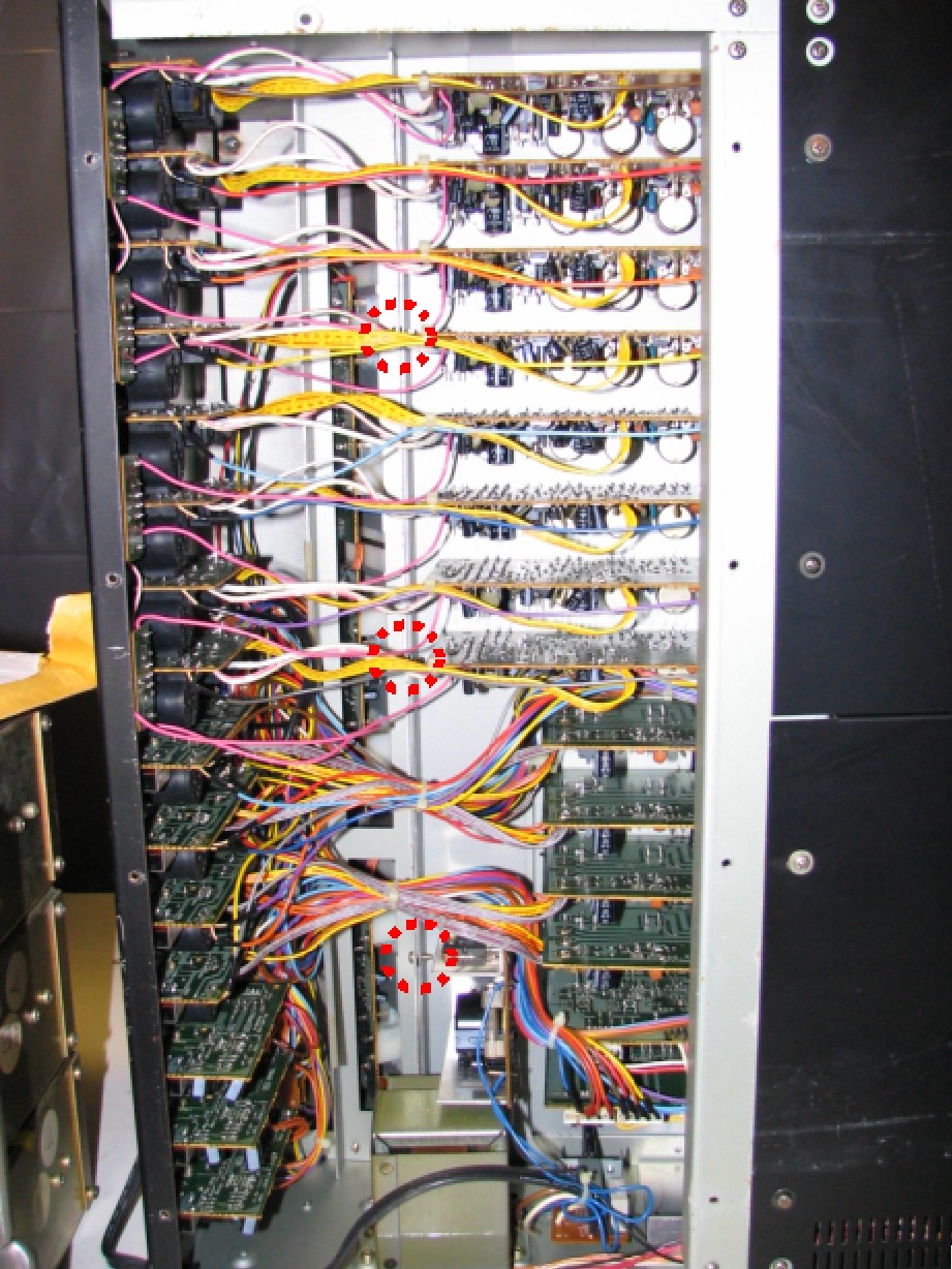
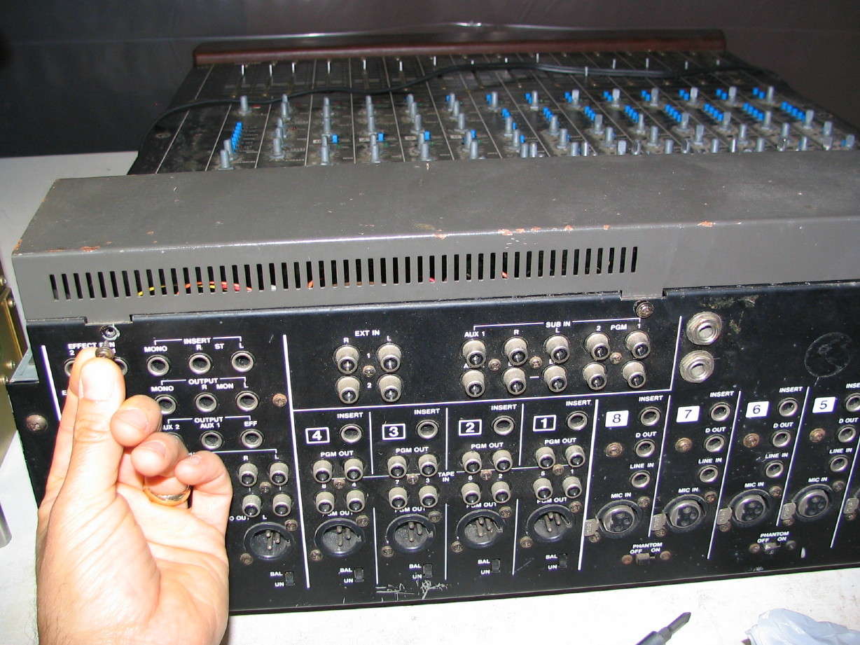
1. The first thing you want to do is tip the mixer on its side, and remove the bottom rear panel. This will expose the back end of the channel cards and such as well as the inside of the jack panel. The bottom front flange of the meter bridge housing is
sandwiched in between the back of the control surface dress panel and an internal cross-member...I circled these screws in red:
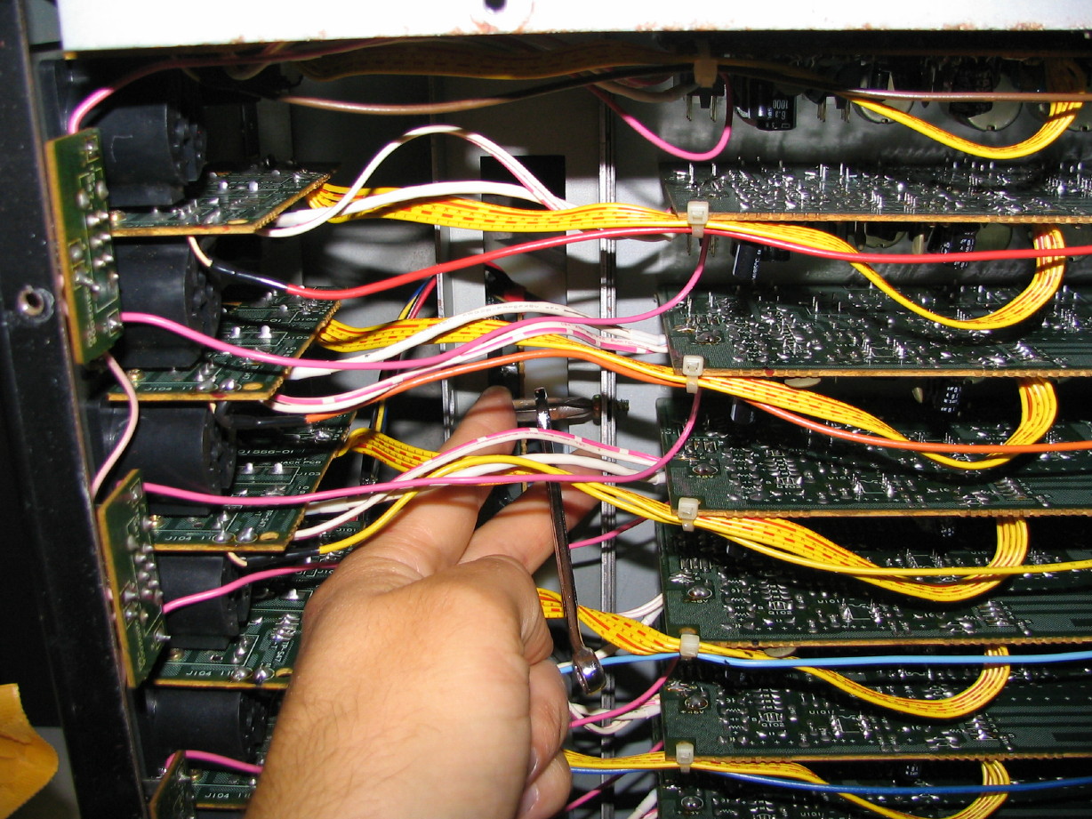
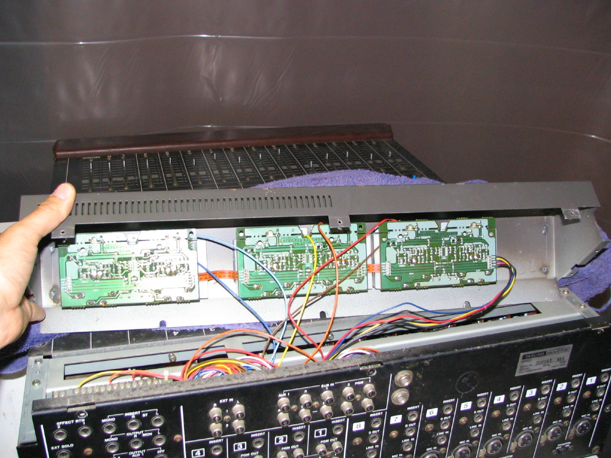
2. Zooming in, these screws are a challenge to get to, but because the meter bridge housing is slotted for the above mentioned screws, you don't have to
remove the screws, just loosen them. Tight space, but I used a #2 philips bit and a 1/4" combination wrench. Hold the bit on the screw head with a finger on one hand, turn the wrench with the other. Do each of the screws. There are 3 on the 308, probably 4 on the 312, and likely 5 on the 320:
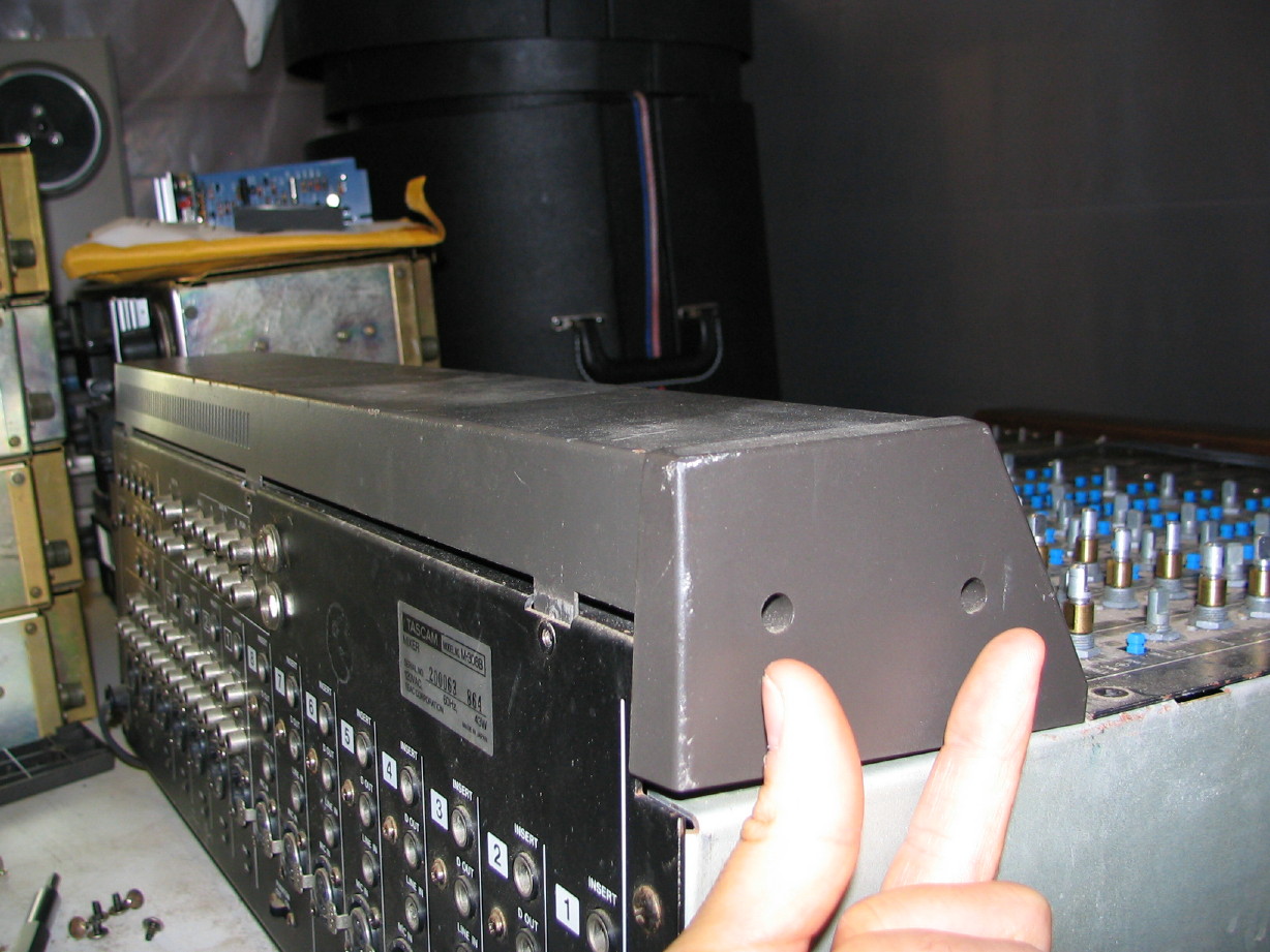
3. Now gently set the mixer back down with the back facing you. Remove the two screws in each of the left and right plastic meter bridge trim caps...these ones:
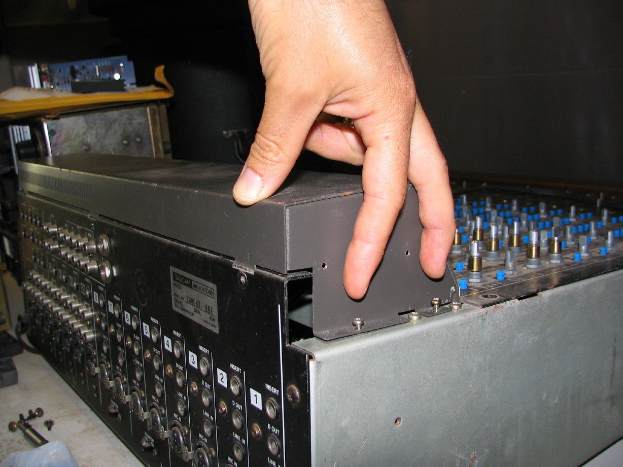
4. Once those are removed you'll see two screws on each side that attach the housing to the side rails of the mixer...take 'em out...4 in all:
5. Now, along the back of the mixer at the top of the jack panel are screws that connect the meter bridge housing to the jack panel. Remove those. Again, there are 3 on the 308, probably 4 on the 312, and likely 5 on the 320:
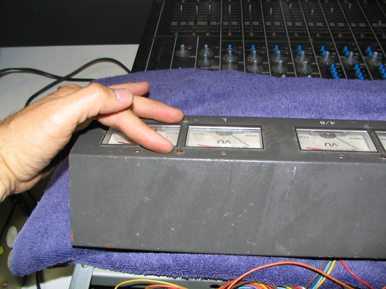
6. You should now be able to work the meter bridge straight upwards. Before you do so, lay a towel across the control surface so you have something soft to lay the meter bridge on...protect that mixer!
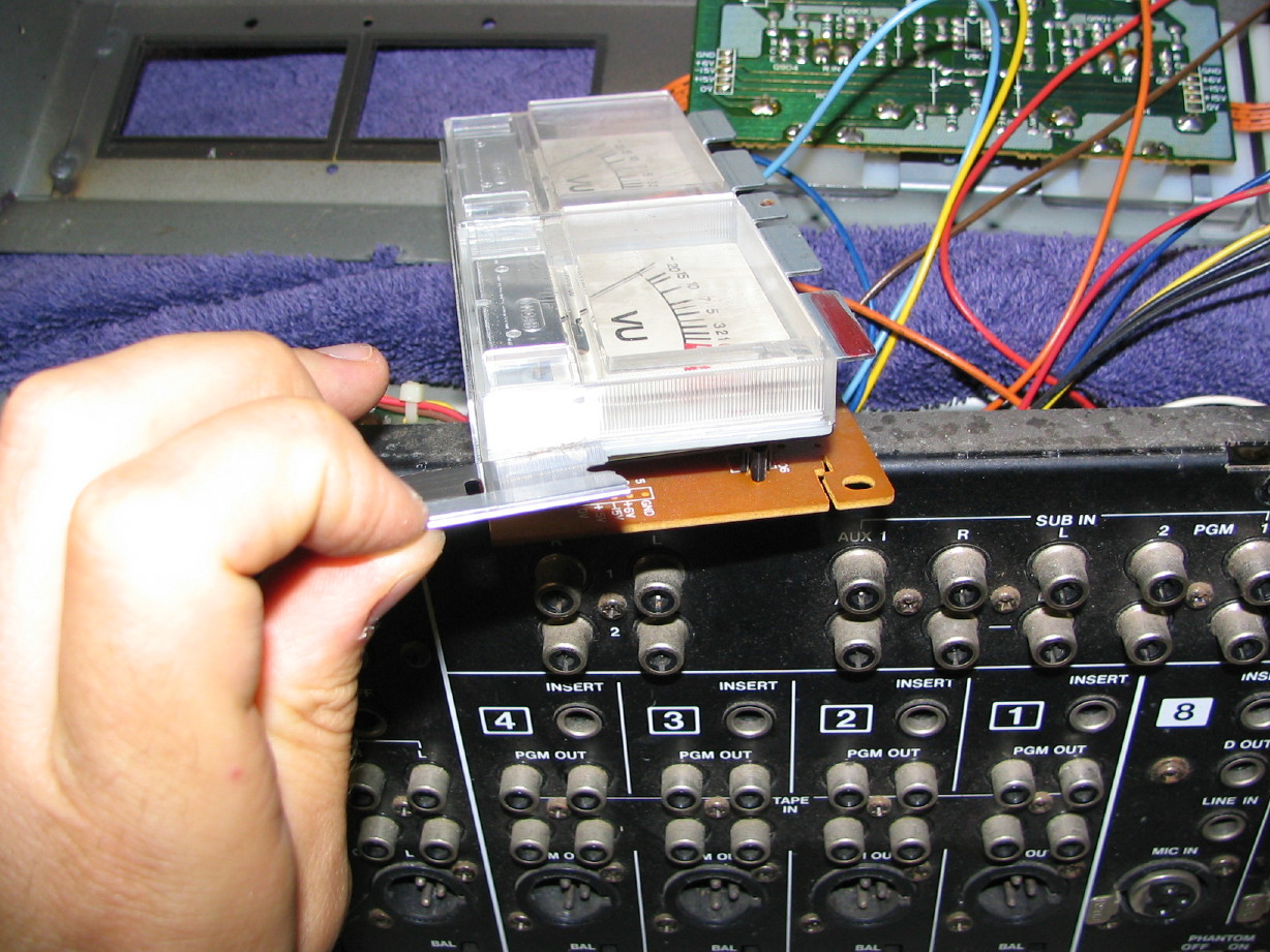
7. The meter pairs are held on by two screws. Take those out and that pair will drop out of the housing:
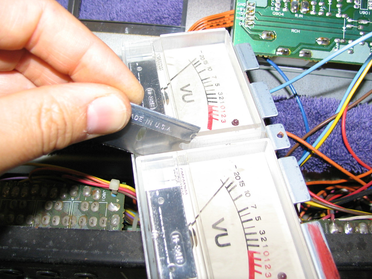
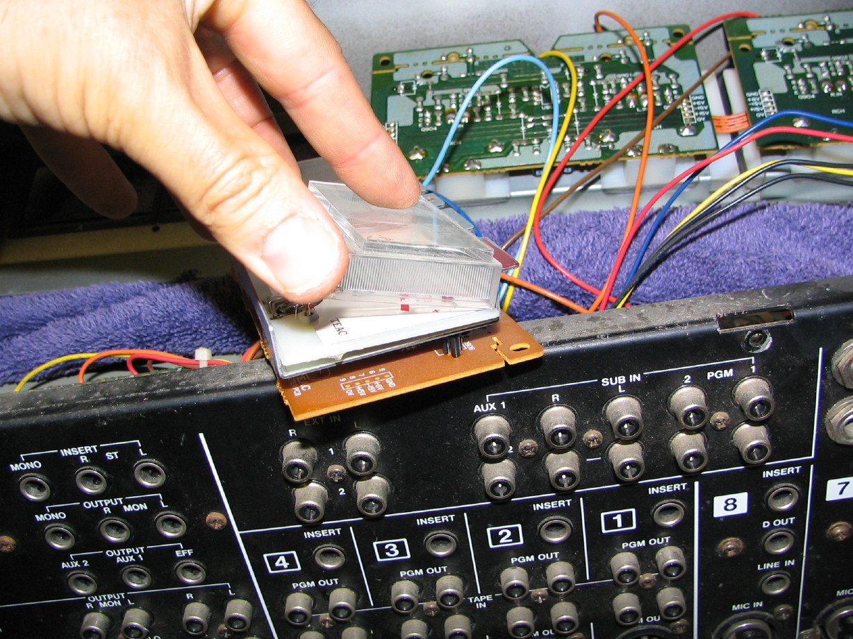
8. Here's where it get's irritating...Unless you want to desolder the VU meter from the PCB (which I don't advise unless it is necessary), its a little tricky to get the meter lense separated from the face of the meter. Teac used a clear tape to hold the lenses on...pretty common, but on the 300-series there are three pieces of tape...one on each side of the lense toward the bottom of the lense, and one on the top middle. Because of the metal bracket that floats between the PCB and the meters (and keeps the meter somewhat aligned) you can't directly access the tape strips in between the pair, or the one at the top. Easiest thing to do is to gently use a razor blade to cut the tape on the sides and then
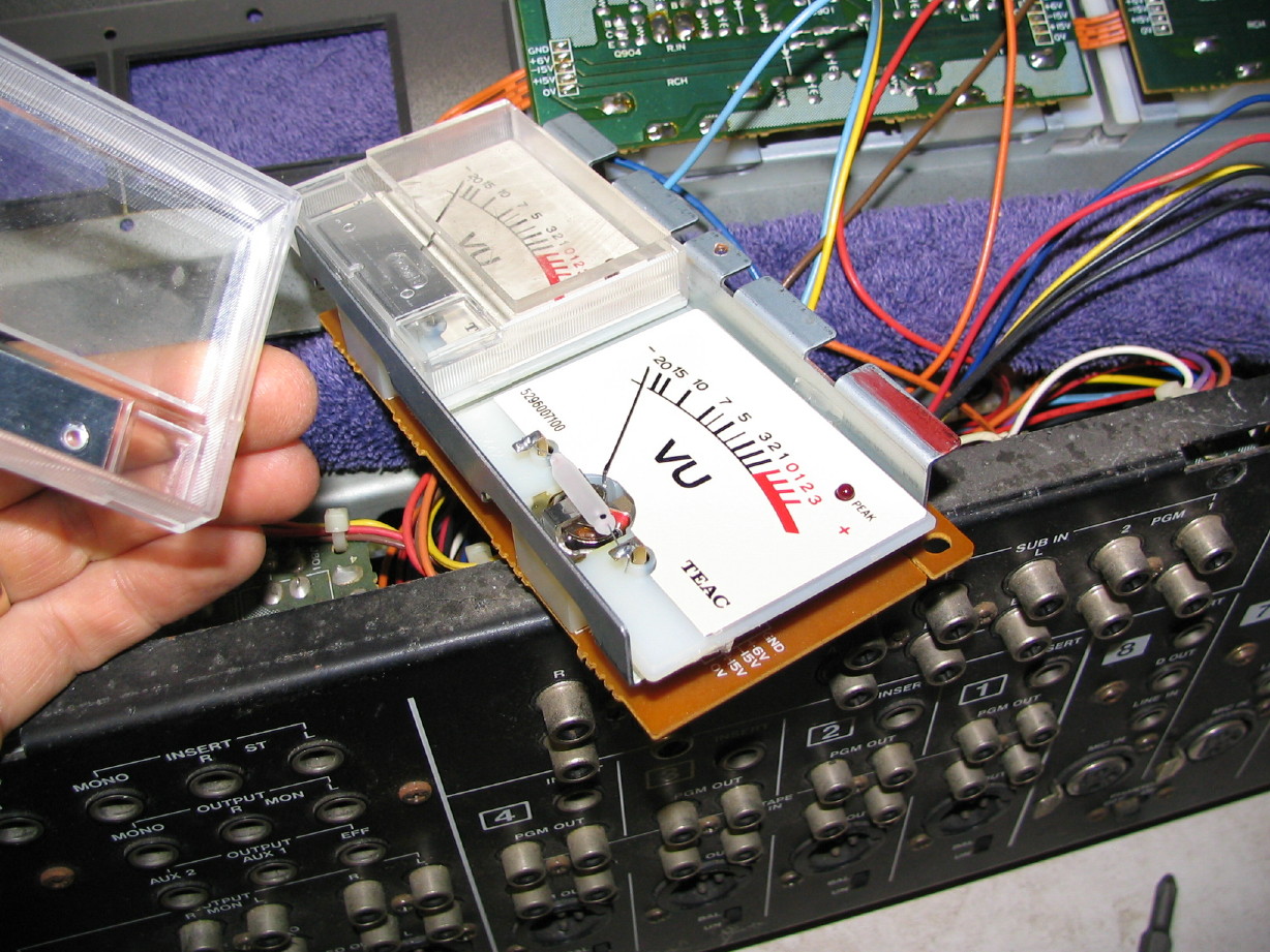
gently lever the lense up at the bottom. If you are careful you can get the lense to separate from the top piece of tape allowing you to lift it free. Be cautious as you don't want to tweak the meter face in the process. Other Teac meters are easier than this. Note: when putting things back together you can use a new piece of tape on the exposed side, or no tape at all. When the meters are back in the housing the whole mess gets held together with hardware. The tape is there to keep things together as it moves down the assembly line IMO. Here are four pictures, step 1 cutting the tape in between the meter pair, step 2 cutting the tape on the exposed side, step 3 levering the lense up, and step 4 the lense finally set free from its bondage:
In that last picture you can clearly see the lamp ready for replacement. Time to turn on that soldering iron! Once the lamp(s) is/are replaced reassembly is the reverse of the above.
")
")