Its time for some more pictures...
Plugging along.
You can refer to
post #67 for some before pics of some of the "after" pics below.
Duddy, not sure if it'll be ready for Christmas.

Though it
has been moved from the unheated shop to the sunroom adjacent to the garage where its new home will be...hard to work on it in 25F temps...
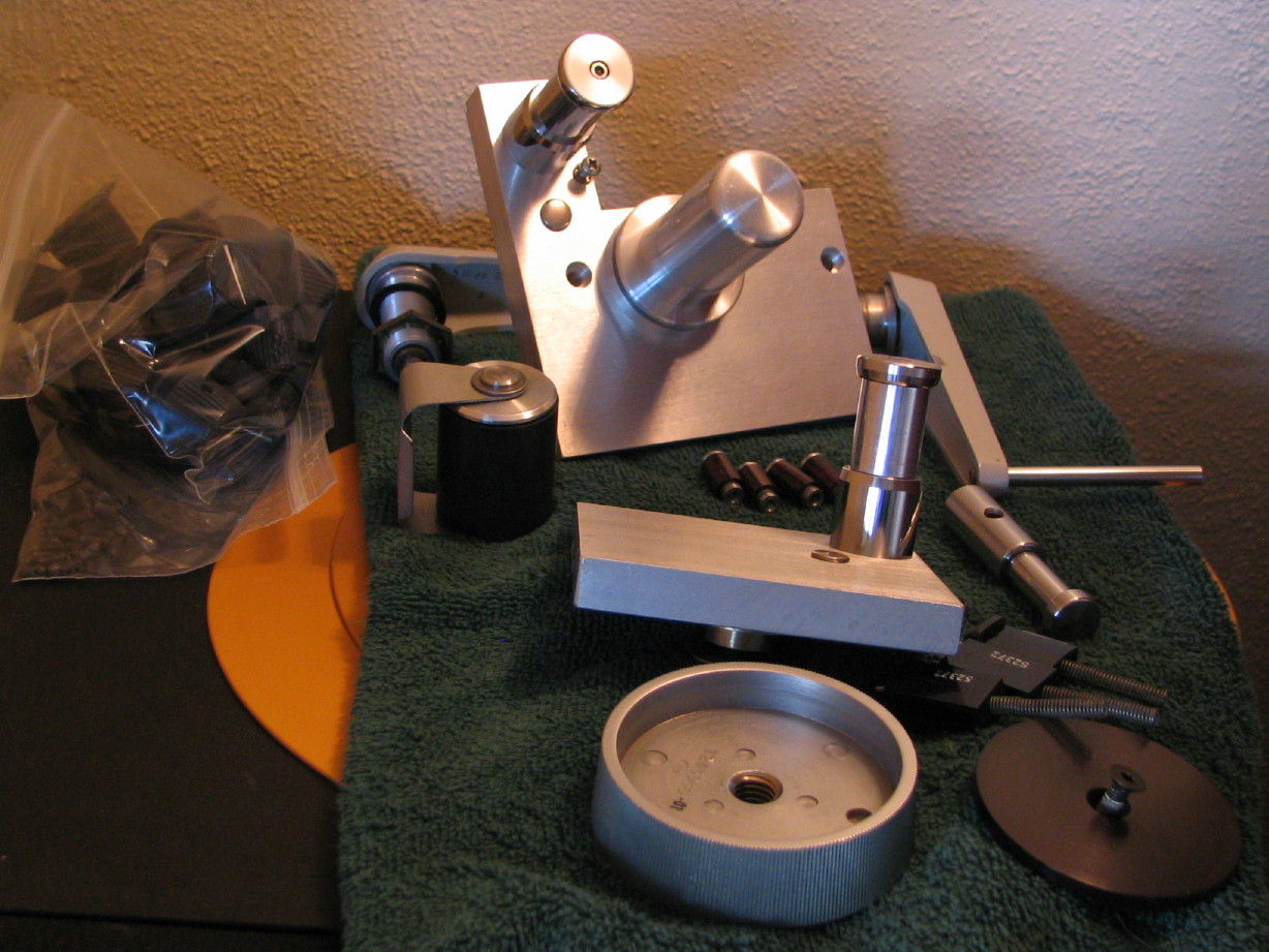
A pile of cleaned up parts to soon be reinstalled...guides, idlers, part of a reel hold-down, tension arms...
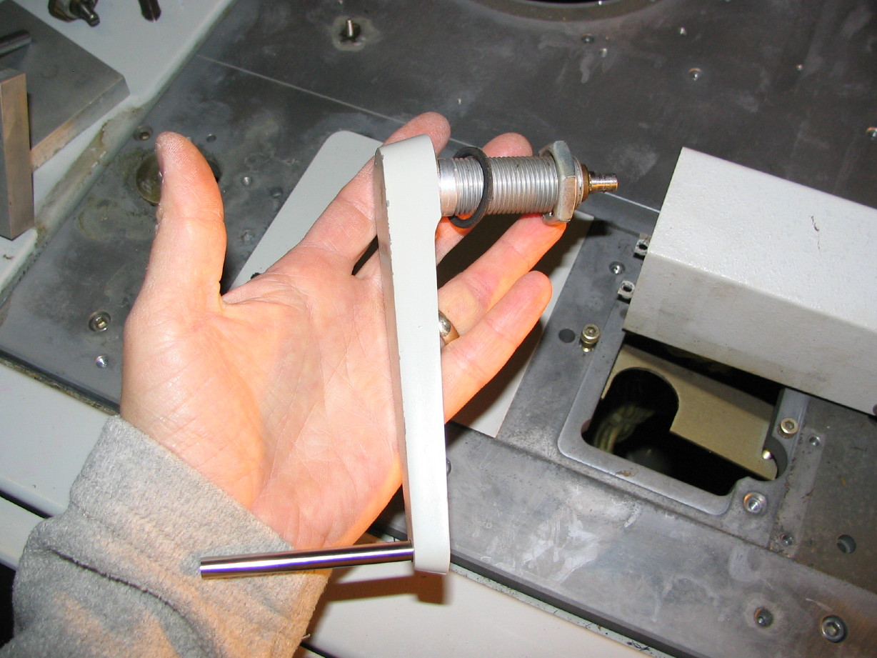
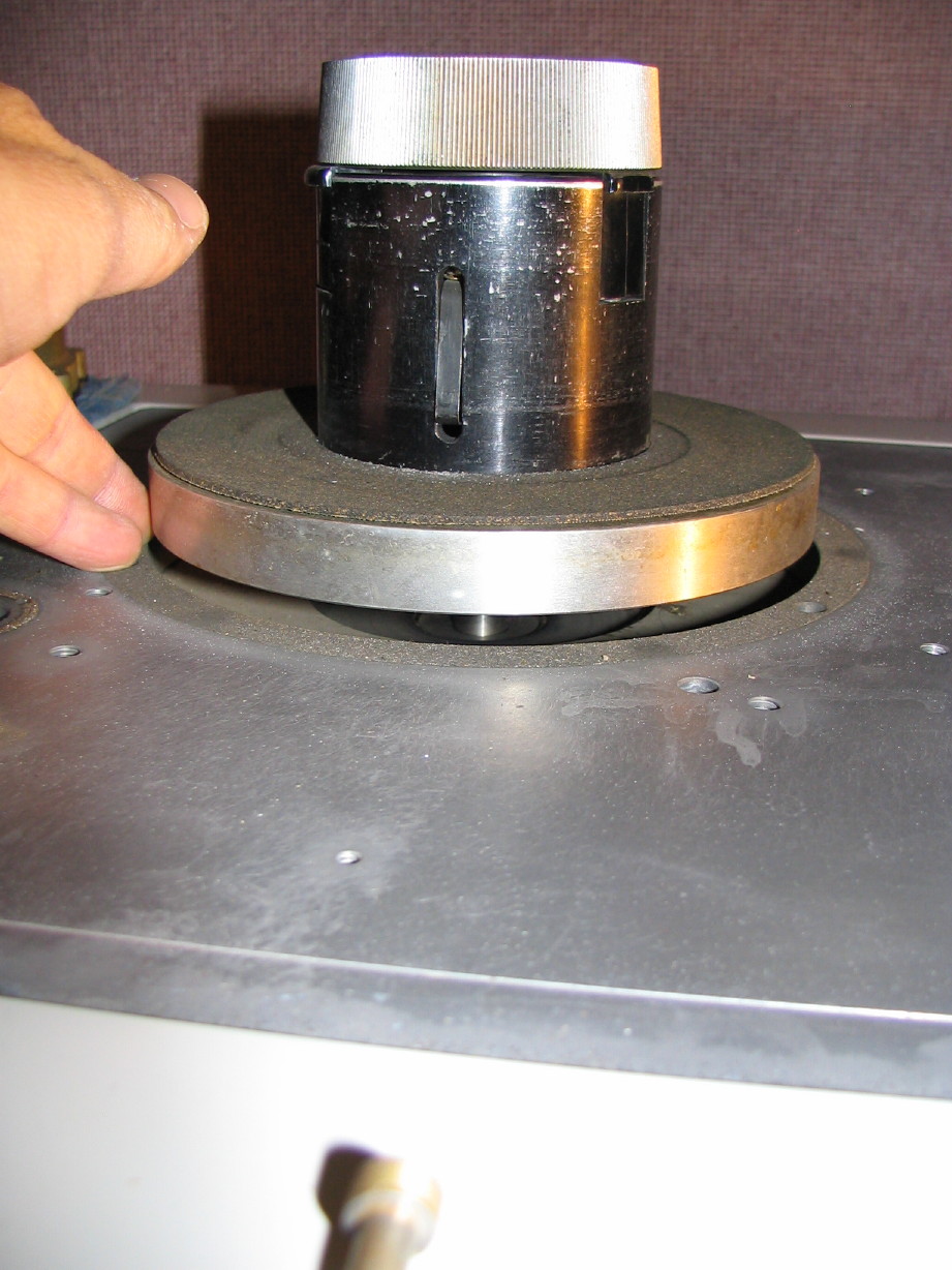
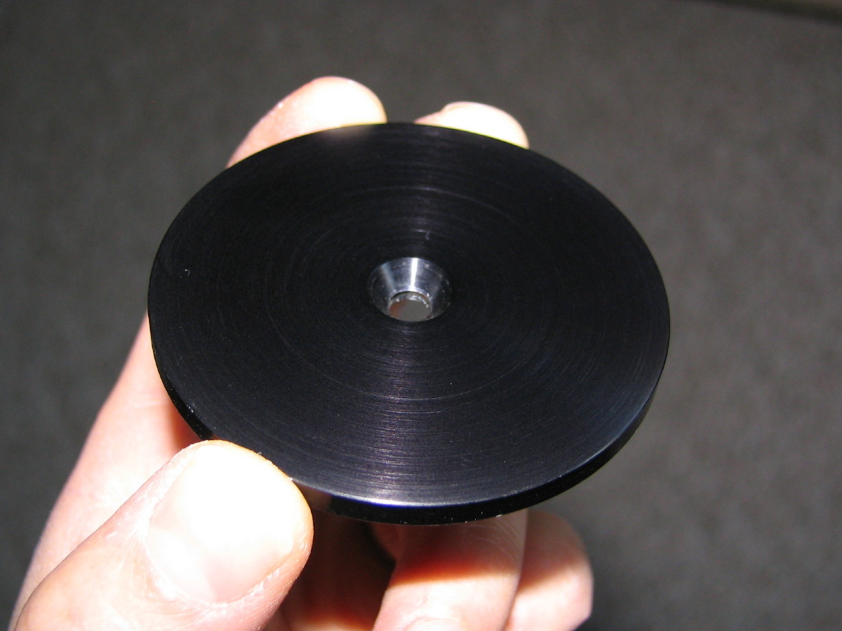
I just had to share this...this is the center cap to the reel hold-down. Its purpose in life is to make sure you don't unscrew the knob too far, and to look nice. They could have done this with a plastic disk...this is a black anodized piece of metal...not sure if it is aluminum or steel but it has a precision finish on it...Overkill and pretty.
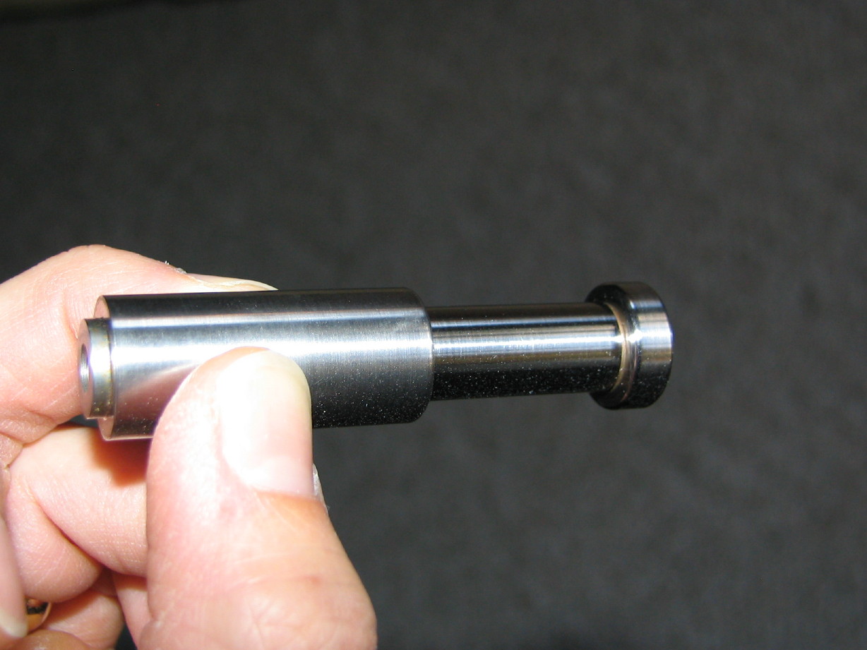
This is the static guide that is in between the counter roller and the takeup tension arm. It was all rusty looking and had sticky shed on it.
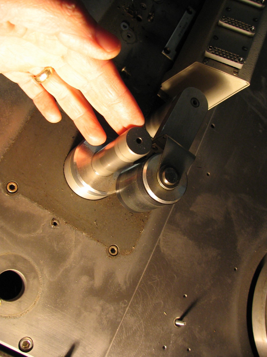
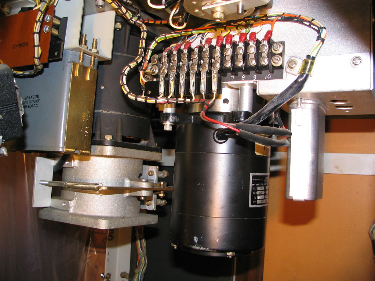
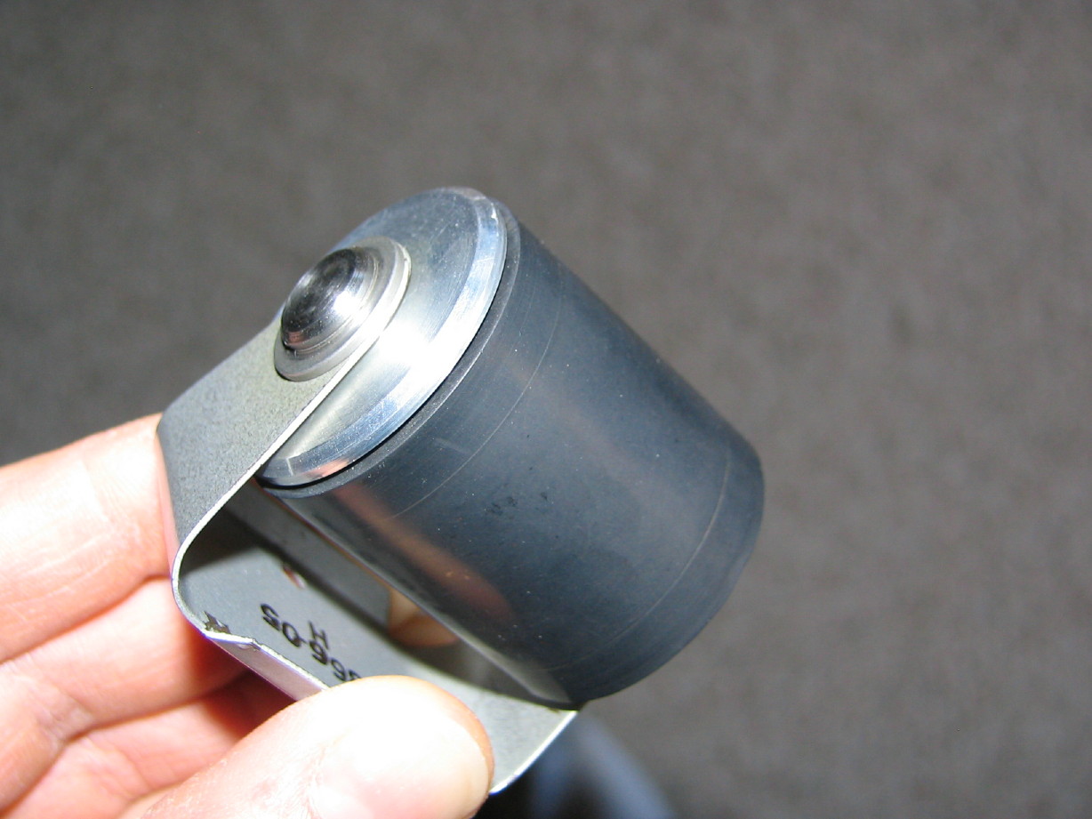
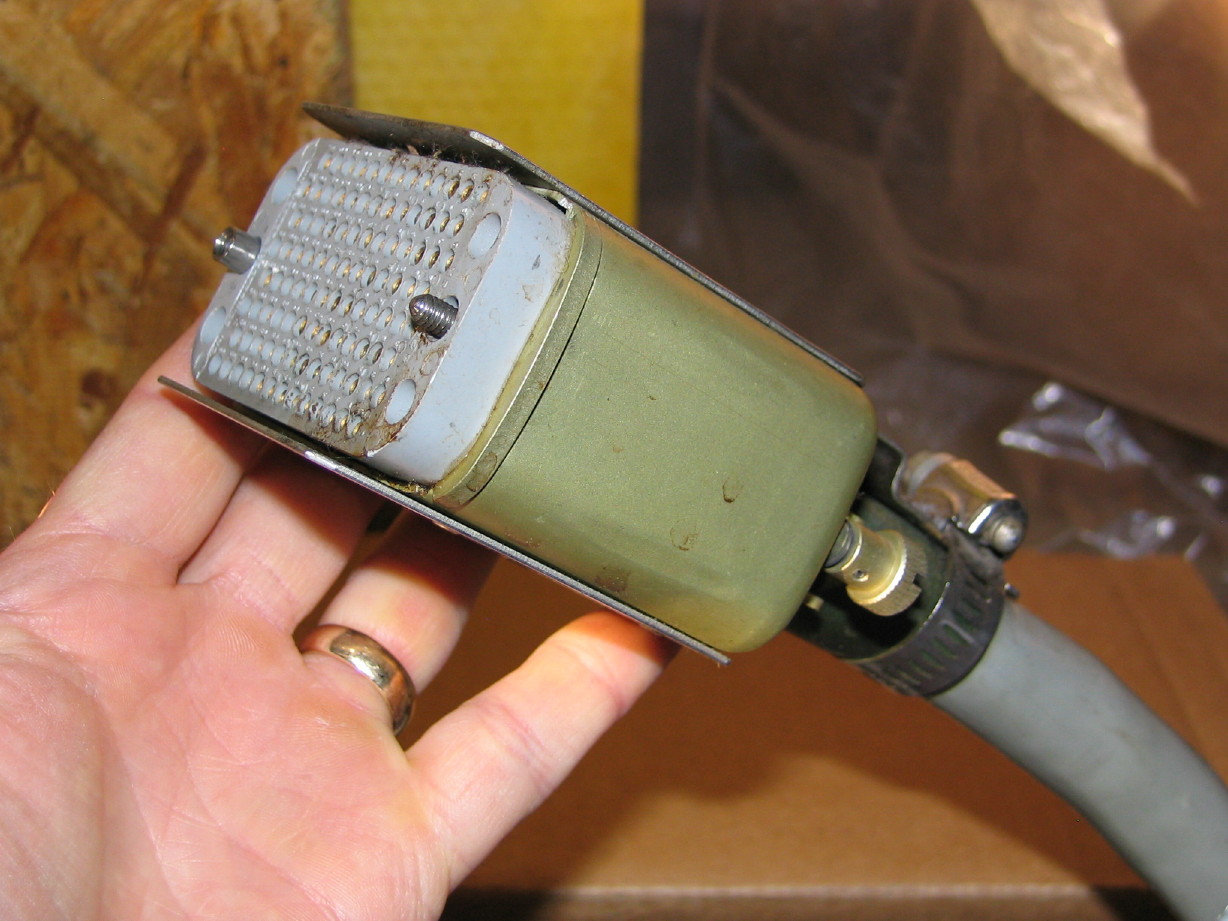
Pinch roller and bracket assembly. Cleaned up pretty good. I think the roller is serviceable but it is still a little glazey. I'm glad I figured out how to get it off the machine though...had to mod an allen key to do it but the alternative is to have to press out a roll pin on the pinch roller arm which is a no-no. Difficult to do without damaging stuff. I'm hoping there is enough adjustment in the position of the bracket when I remount it on the arm because I noticed before removing it that the axis of the roller was not the same as the capstan shaft so the roller would touch the shaft at the bottom but there was a slight gap at the top. I think it is a mounting issue and not that anything is damaged.
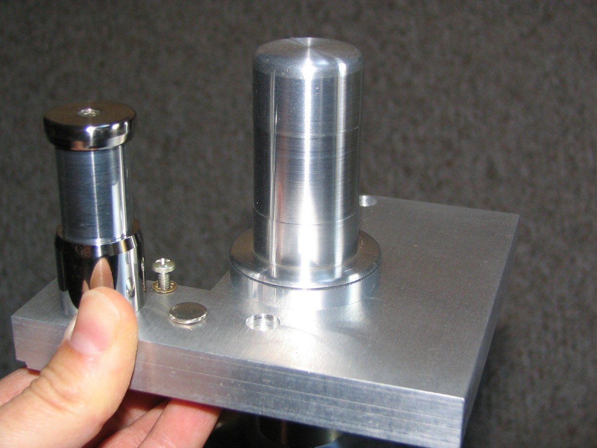
This is the mounting plate with one of the rolling guides and reel idler roller just prior to the headblock.
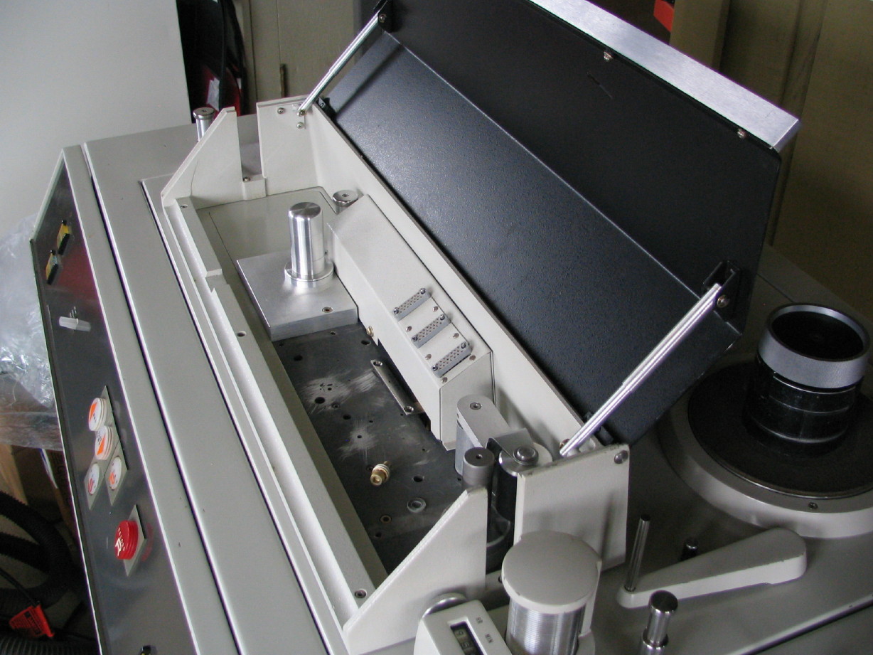
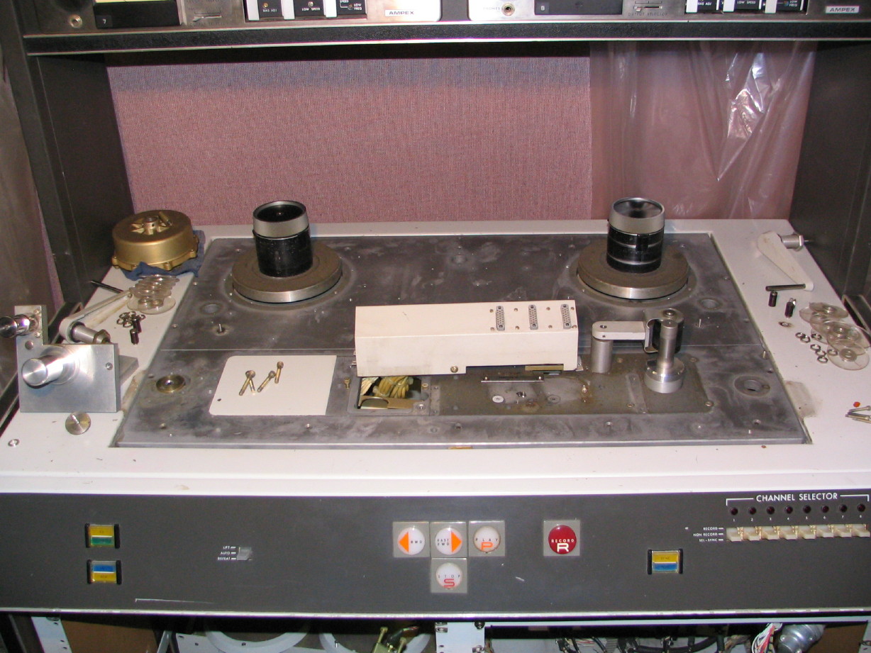
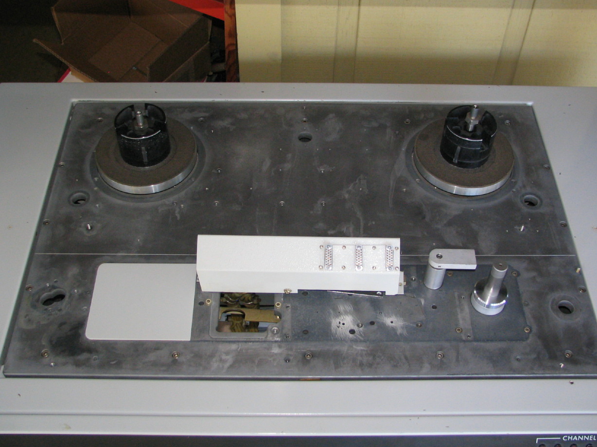
Here's how the transport plate looks at present...maybe hard to tell but there's a lot less dirt and yuck on it. Interestingly enough I realized that the sides of the inverted "box" that makes up the transport plate are actually bolted on with healthy-sized socket head cap screws...you can see them around the perimeter of the plate...all precision stuff. Makes sense to do it that way because when you weld metal the metal tends to distort and pull toward the joint as it cools...probably would be difficult to keep a precision surface or remachine the surface if the box sides were welded on.
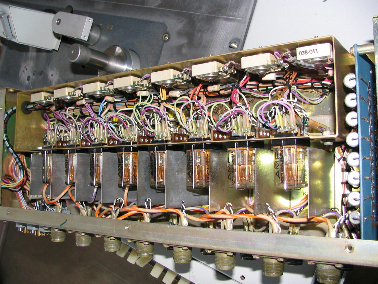
On to the sync module...this is the 2U rack-mount box that mounts at the top of the lower-left rack in the console and I
think its purpose in life is to simply bring several of the components/adjustments of the electronics modules to one place that is in the
front of the machine. The relays in there I
think are the record relays, and also in this box are the sync level trimmers and the sync bias traps...this box might also have something to do with the record and sync enable functions on the remote. I need to study the schematics to understand what all this thing does, but it'll be nice not to have to climb around the machine to adjust these things. Now here's the point...
lookit how clean it is...! I'm not kidding...it was pretty scungy on the outside, at least on the faceplate, but inside it looks new. Pretty good for 40 years old.
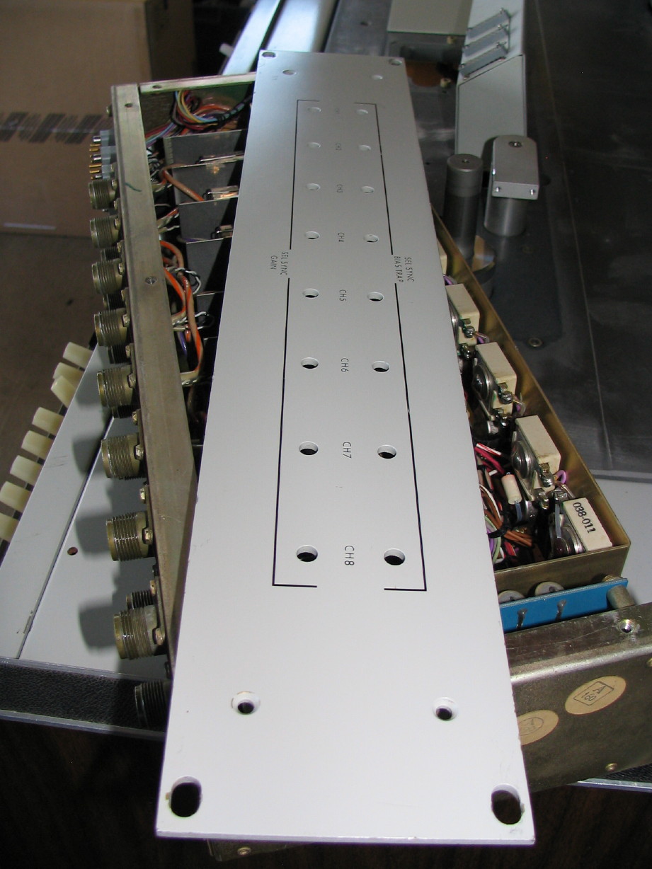
And here is the faceplate after cleaning it up:
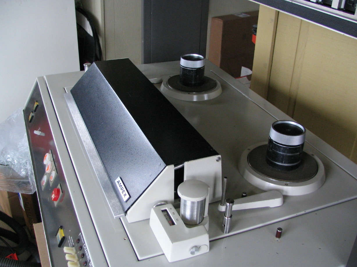
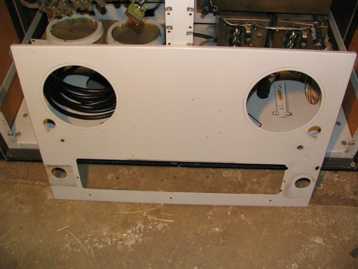
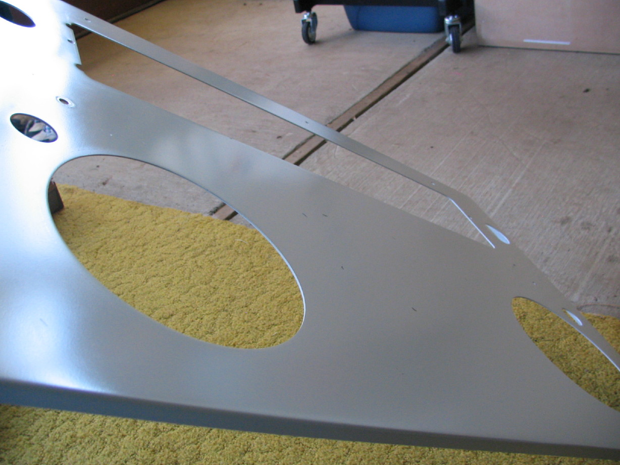
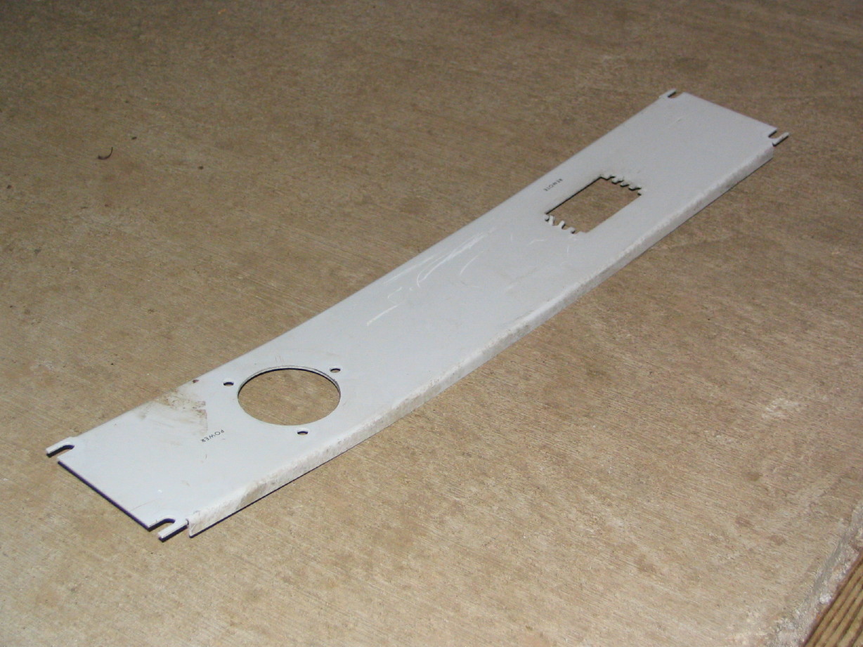
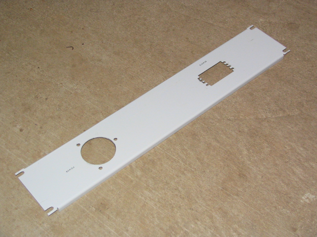
Here's a pic of the transport dress panel all shined up that I mentioned in the last post:
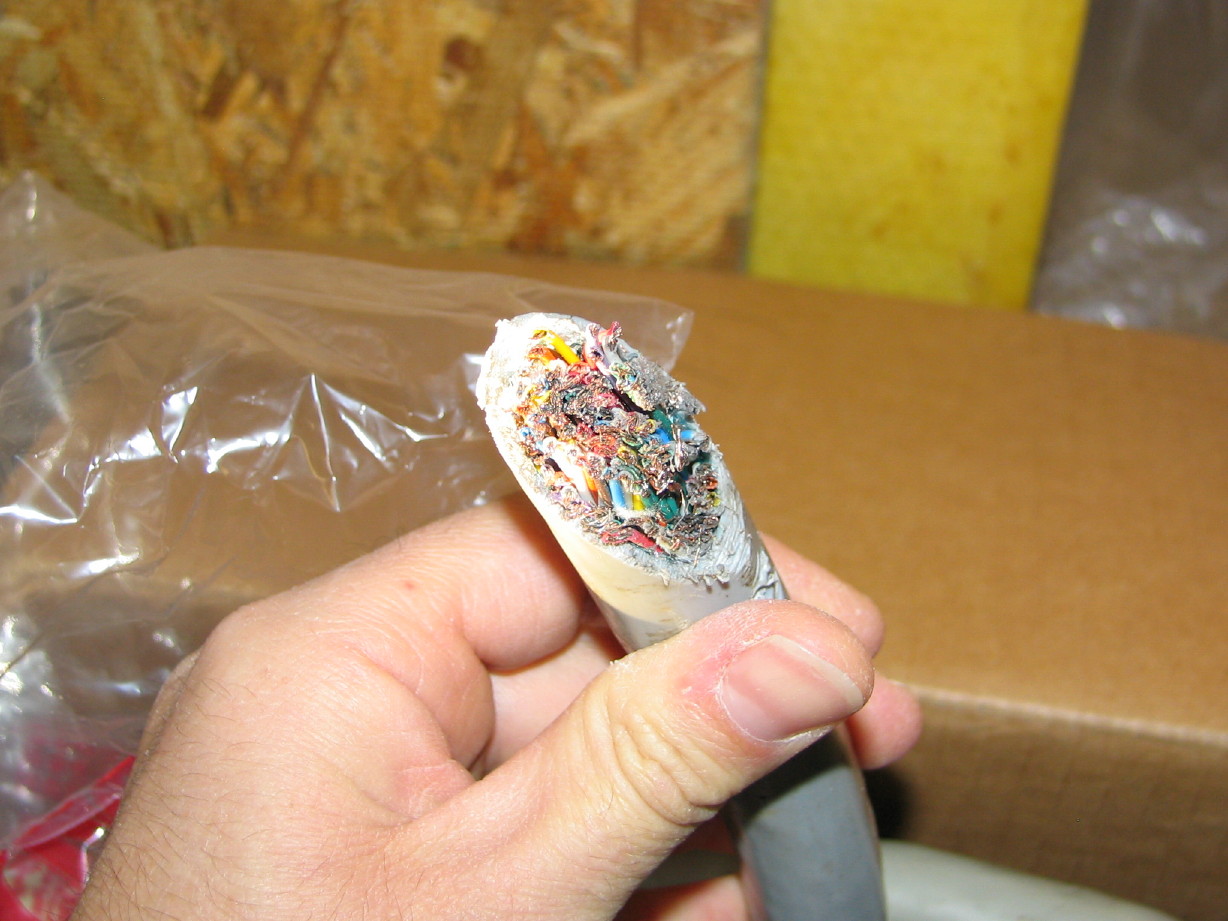
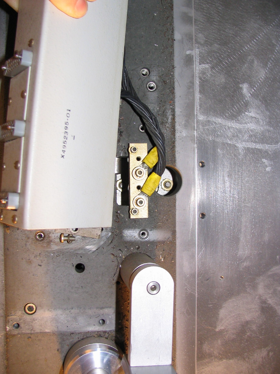
And in the "everything's bigger on an old Ampex" category, here's a shot of one end of the remote cable I recently sourced:
The remote cable has a catch...it has been accidentally cut in two which is why I only paid $50 for it. Think I'm nuts? 104 conductors, spendy Winchester connectors, 24' in length. It was cut into one 4' piece and one 20' piece during a salvage operation. But, for certain, the parts alone would cost WAY over $50, and all I need to get to fix this is a bag of the pins and I'll have a 20' remote cable which will do me fine. It'll be a project, and fortunately I don't really have any need for the remote any time soon so this will go on the shelf for later but I snapped it up because cables like this, when you can find them, tend to go for $200 to even as high as $300. Here's a shot of a cut end. Fat cable. Yep.
I leave you with this thought...Nobody builds machines to break down right? As consumers we expect our equipment to be reliable. I was pondering the other day the whole reality that the MM-1000 was based on an Ampex quad video machine and whether or not that seems kind of kludgey, but really, if I think about a professional A/V environment in which you would consistently
absolutely have to have equipment that will run without fail wouldn't it be in professional video broadcast? Think of the advertising machine that drove and continues to drive that marketplace...no slip-ups allowed...Ampex quad video machines were an industry standard and had been field tested years and years over before Ampex used one as a bed for the MM-1000. Yes they did it in a pinch to meet a dawning demand for larger format audio production machines, and the MM-1000 was arguable TOO big, but it also seems to be they weren't haphazard in their selection of off-the-shelf parts/systems to quickly bring something to market. And I'm not saying that audio production is/was a lax environment...lots of dollars and pressures riding on every minute of studio time, it just seems to me in my mind that the scope becomes larger when you are talking about video broadcast gear vs. multitrack audio production gear.
")

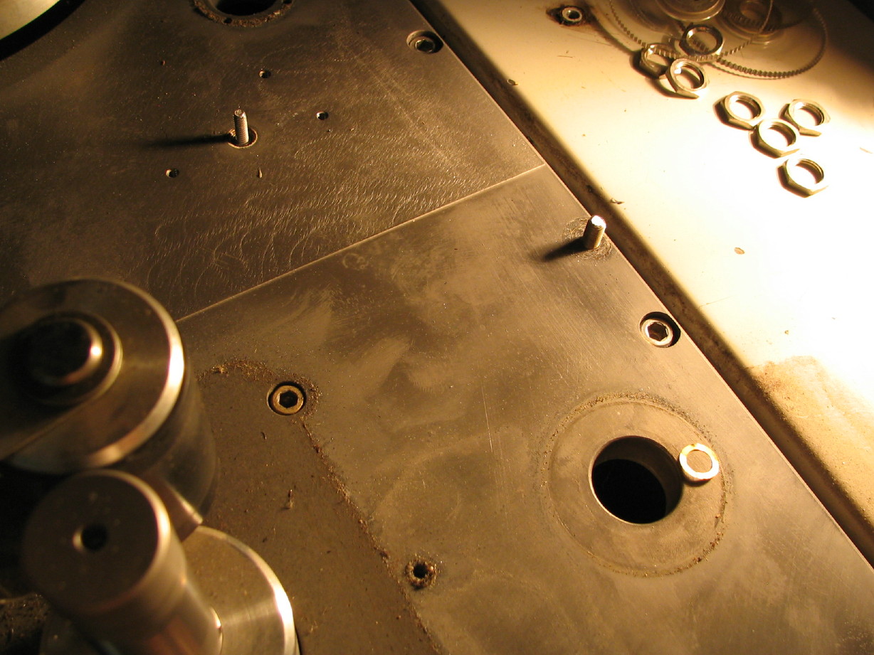
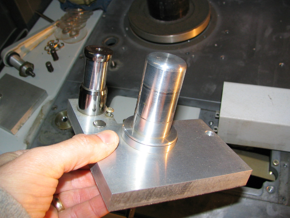
 And look...there is an additional thick aluminum mounting plate in addition to the thick transport plate. Oy.
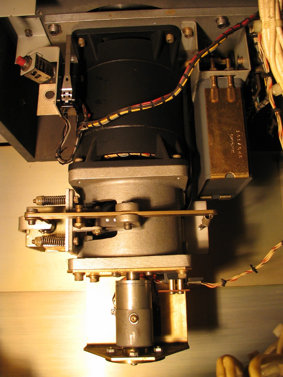
")