Hey S8-N, I am giving another class here.....
")
Your path bays come "half-normalled" which is perfect for several applications. Unnormalled will be used for some applications. Fully normalled will not be used at all. So here is the deal.
The purpose of the path bay is two. One, the make a normal signal route for you. Two, to give you the ability to access that signal path to have the option of going somewhere else with the signal with or without returning it to it's destination. Sound confussing? It might but I will explain.
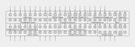
In a "normalled" configuration, the top and bottom jacks are connected together. This would be used to say go from the output of your console to the input of the tape deck. You don't need to do anything to complete this connection except to hook the cables up to the back of the patch bay. The proper way of doing this is the plug the output of the console to the top jack, and the input of the tape deck to the bottom jack.
Now, you can use a patch bay to run from the output of the tape deck to the input of the console. You would do this by connecting the ouput of the tape deck to the top jack and the input of the console to the bottom jack.
Now that you are all connected, you can start using the patch bay to insert something in between the destinations.
Let's say that you are tracking and you feel that you need to hook up a peak limiter before you get to tape. All you would have to do is on the front of the patch bay that is configured for console to tape deck, take the top jack for whatever channel you need the limiter on and run a cable from that channels top jack on the patch bay to the input of the limiter. From the output of the limiter, you would heek up a cable to the bottom jack of that channel on the patch bay. Vola!!! You have now inserted a limiter into the signal path.
You may notice something though. The limiter will not be inserted untill it's output is connected to the bottom jack on the patch bay. That is because the "half normalled" connection at the patch bay that connects your console output to the input of the tape deck is not broken untill something is plugged into the bottom jack on the patch bay.
So, let's say that not only would you want channel one on the console to go to track one (you already have this hooked up on the patch bay by following the above wiring) but you also want to send that track to something else like a drum module or something. Well, you can access that tracks source from the console via the top jack on the patch bay without affecting that source from getting to the tape deck. You see, the top jack on from just gives you access to the source signal. The bottom jack is an interrupt to the destination. using them both acts like an insert. Cool!!!
Next. Un normalled.
Usually you use unnormalled configuration for signal processors such as compressors, gates, limiters, etc......Unnormalled means that the connection is not made between the top and bottom jack on the patch bay. The reason for this is because processors don't like to have to output feeding back to the input. So, you have to have a way of accessing the input and output of the processor without the two being halfnormalled.
Usually (and this is the case with all the above named patch bays in this thread) you unnormal the patch bay by simply taking the curcuit board and turning it upside down. It is that simple. Now the output of a device will not feed the input. Actually, by doing this the input feeds the output which is okay.
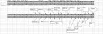
So let's say you have a Re an 48 point patch bay, one 8 track machine, two stereo processors, and one stereo effects processors. Here is what you would do to make it all fly on the same patch bay.
Tape output's 1-8 of the console would go to the top jack (on the back of course) 1-8 on the patch bay. Input's 1-8 on the tape machine would go to the bottom jack(you got it, on the back) or the patch bay. Bam, 1-8 is all hooked up. The outputs of the console will go to the input of the tape deck automatically without any patching.
Next. Output's 1-8 on the tape machine would go to the top jack 9-16 on the back of the patch bay. Tape return 1-8 on the console would hook up to the bottom jack 9-16 on the back of the patch bay. Bam!!! Now your tape deck will automatically go to the console without any patching.
Next. 17-20 on the patch bay need to have their curcuit boards turned upside down. Now, you would use 17 and 18 for channels one and two of the first processor, and 19 and 20 for the second processor. Remember, processor input to the top jack, processor output to the bottom jack. Bam, processors are working.
Next. Take your aux sends one and two from the console and go to the top jack 21 and 22 of the patch bay and the effects unit input will hook up to the bottom jack of 21 and 22. Bam, automatic effects sends from the console to the effects unit without patching. Next, effects unit left and right out to top jack 23 and 24 on the patch bay, and whatever you would normally use for a effects return on your console to bottom jack 23 and 24. Bam, instant effects return.
So, if you wanted to compress track one before going to tape, plug in a cable from the top jack of one and run it to the top jack of 17 (left channel of your first processor) and hook up another cable from bottom jack 17 to bottom jack 1. Bam!!! Your compressor is "inline".
Now let's say that you are mixing instead and you want to compress track one.
You would hook up a cable from top jack 9 to top jack 17, and another cable from bottom jack 17 to bottom jack 9. Now the compressor is in between the tape deck track one and the console's tape return one.
While mixing, you could run a track directly to a effects processor just by tapping into it's input's and output's just like above.
You could plug an instrument like a keyboard directly into an effects processor and run it to to mixing board, or to the tape deck.
Get it??? You have all of your input's and output's on a jack where you can access it, and all of your normal connections you need to make are already made for you for a normal tracking or mixing environment. Cool!!!
Geez, I otta right a manual!!!
Ed Rei
Echo Star Studio
www.echostarstudio.com