MXL Guitar Cube - Need help

Stogie_D

New member
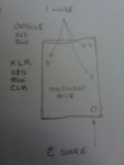
Hey all, hope someone here can help me with this. I bought a MXL Guitar Cube at a garage sale the other day for 30 bucks. Person said they did not know if it worked or not. I have wasted 30 bucks on less so I bought it. Brand new in the factory box with all accessories including the book & wiping cloth. Hooked it up & no signal. After swapping Mic's, cables, channels & whatever else I could think of, no signal. I spun off the bottom retaining ring & took off the bottom cover to have a look. Check this out - it was never wired at the factory. PC board has never had a wire inserted & soldered. All wires are there & tinned properly, just not inserted & soldered. 5 wire holes & 6 wires. I think thats right, not looking at it right now. 5 holes are sized for 1 wire & 1 hole sized for 2 wires. I would love it if anyone that has one of these would take a look at theirs & tell me which wire goes in what hole. I have no problem soldering this up, just need to know where they go. MXL will not send me a schematic & don't seem to want to help. All wires insert on the component "top" side & solder on the "bottom" or solder side. A rough drawing would do fine as long as we are looking at the component side. A written explanation would work, orient from the hole for 2 wires. Don't know if this mic is worth a crap or not but would still like to get it wired & try it.

Appreciate any help.
David
 
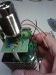
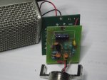
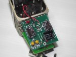
Wow, 99 views & no one has one of these? - They must suck :) let me update, it's 5 wires & 4 holes in the PCB. Red & Blk from the capsule & Red, Blk & Clr from the XLR. See pics, maybe this will help. Still hope someone has one & will take a look at theirs. D.!cid_P82A06581.jpg!cid_P82A06571.jpg!cid_P82A06551.jpg
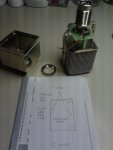
 
Hopefully user ecc83 sees this. Sometimes I think he sleeps with a soldering iron in his hand.
 
Pay no attention to the view count. They are inaccurate and misleading.

I've got an old MXL V57M which I won't mind taking apart to see how it's wired up. I imagine the circuitry is probably the same or similar. I'll try to get to it tonight.
 
Those pics are exactly what mine looks like....

I think the big three holes are used for strain relief.
 
Morning fellas. Thanks for responding. I do not have a ohm meter. I am not an electronics guy but real good with a soldering iron from making cables forever. I did find a good picture of a Drum Cube, these are supposed to be very similar. The Drum Cube has 2 PC boards in it, the Guitar Cube I have has only 1 PC Board. I really need inside pics of a chrome Guitar Cube Pro to see if this one is complete or not. I'm starting to think this one may be missing some parts. Although, as i said earlier, the PCB has never been wired. Marshall Electronics Tech Support is no help at all. I appreciate the schematic but I can't match it up with what I have. It does appear that the copper at the hole sized for 2 wires runs about 1/2 inch & there is another hole for 1 wire with no components in between. Still looking for some images of the exact same mic. D.
 
Yes, there should be two PC boards. And you have only one of them. Please take a look the attached photos.

mxl2.jpgmxl1.jpg

Mark
 
If you look carefully at the board you have, you will find that this is the DC-DC step up converter from the schematic in post #5 (left lower corner). So you have only DC-DC converter but you don't have the preamp. The preamp is different from the posted schematic because it is build with integrated circuits. The input circuit is most probably AD8615 opamp (in SOT-23-5 package) from Analog Devices.
I think that it would be the best to sell what you have (for parts) to guys who build microphones.

Mark
 
Last edited:
Back
Top