HELP! MXL Genesis Power Supply Repair

Fenderguy81

New member
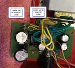
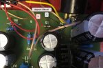
Hey guys I have a MXL Gensis mic that was humming so I opened up the power supply and found what looked like a bad capacitor. I changed out the 2 larger caps with the same value and now the power supply is not powering on fully. The switch is lighting up where the AC cable is inserted in the back, but the red LED in the front is not lighting up. I tried reconnecting the mic and no signal is passing through. Any advice on where to start looking?

Thanks!
 
Check the bridge rectifier?

A bad cap in a PSU is due to old age or a blown rectifier, usually.

But that's supposing this isn't a swtiched-mode PSU.
 
Below is a schematic for an Apex460 tube mic (couldn't find one for the Genesis). Might be similar (or not).
Top section is the power for the tubes 12vdc heater, lower section for tubes plate supply. D12 is an LED which is the pilot lamp and powered from the 12vdc. Did you change out two fairly large value caps that may have been on the 12vdc section? The larger caps are polarized + & - and should be installed the way the old ones came out.
Have a meter?

Caution.... High Voltage in there!!!!
 

Attachments

  • smapex460-2.gif
    smapex460-2.gif
    20.1 KB · Views: 82
1.jpgThanks for the info guys. I replaced the two larger caps on the end to the left. I made sure to put them in the same direction as the old caps. I do have a multi-meter, which I was able to use to check continuity on the circuit board. Beyond that, it's a bit over my head, but if anyone has any advice I am willing to try to test/troubleshoot further. Here's a picture of the power supply.
Thanks!
 
The component names on the circuit board look to be the same as the schematic I posted. It may be a generic PS that works for a few different mics. Put it back together and the diagram below shows some points to check on the low voltage side which supply's the voltage to the pilot lamp which doesn't work.

The PS appears to have a voltage selector switch. I don't know where you are located to guess the AC mains voltage. Any chance the switch got bumped up to a 240vac setting and your mains are 120vac?

If your meter doesn't 'auto-range', set it to something like a 20-25 volt range and on DC. Put the tip of the meters red(+) probe to diode D7 on the end that has the ring, black(-) probe to what I think is diode D8 on the non-ring end. The meter should read something higher than 13-14 vdc, maybe up around 18-22vdc. This checks the bridge rectifier is putting out some DC. If you don't get any DC at that measurement point, set the meter to AC at a range of 20-25 vac and measure the non-ring ends of diodes D7 and D9 (careful not to touch the probes together so as to cause a short). Guessing around 20-22 vac. If you don't get the AC I'll suggest some other points to check on the other side of the transformer. If you can try to relate the names of the components to the schematic you may be able to follow and get an idea what is connected to what.

!!!!!! Do remember when it's powered up there is high voltage that will not feel good if a finger is poked in the wrong place. !!!!!!
 

Attachments

  • 1v2.jpg
    1v2.jpg
    243.8 KB · Views: 33
It is a great pity that you did not establish whether the hum was on the HT or heater line.
THE most likely components to fail in the PSU are the 7812 regulator and D11 (I can only work from the schematic provided) or the zeners, D5/D6. DO NOT FFS connect the mic until you have metered ALL the connections!

So, is D12 alight? If not check the output of the reg on C8. Nothing? V on C7. If STILL nothing check the AC on the bridge diodes, 7,8,9,10. If still nothing you have somehow 'ucked the traff winding. If you DO have 12.6V DC...

Check voltage on C5 if more than about 200V the zeners are O/C and THAT was the original cause of the hum.

N.B R4, 1meg is a drain resistor and IMO should be a 2 watt type. I would replace and upgrade it to 2W Metal Film as resistors in this position, under constant high voltage stress often go O/C even when well rated.

And yes! Be careful. A short 200V shock probably won't kill you unless you have a heart condition but it will knock you on your arse and bloody hurt!

We need pictures and voltage tables.

Dave.
 
The component names on the circuit board look to be the same as the schematic I posted. It may be a generic PS that works for a few different mics. Put it back together and the diagram below shows some points to check on the low voltage side which supply's the voltage to the pilot lamp which doesn't work.

The PS appears to have a voltage selector switch. I don't know where you are located to guess the AC mains voltage. Any chance the switch got bumped up to a 240vac setting and your mains are 120vac?

If your meter doesn't 'auto-range', set it to something like a 20-25 volt range and on DC. Put the tip of the meters red(+) probe to diode D7 on the end that has the ring, black(-) probe to what I think is diode D8 on the non-ring end. The meter should read something higher than 13-14 vdc, maybe up around 18-22vdc. This checks the bridge rectifier is putting out some DC. If you don't get any DC at that measurement point, set the meter to AC at a range of 20-25 vac and measure the non-ring ends of diodes D7 and D9 (careful not to touch the probes together so as to cause a short). Guessing around 20-22 vac. If you don't get the AC I'll suggest some other points to check on the other side of the transformer. If you can try to relate the names of the components to the schematic you may be able to follow and get an idea what is connected to what.

!!!!!! Do remember when it's powered up there is high voltage that will not feel good if a finger is poked in the wrong place. !!!!!!

Thanks for the help! The 240vac switch got bumped at some point and is now back to 120vac. I measured D7 and D8 on DC as you indicated and got 14.33.
 
It is a great pity that you did not establish whether the hum was on the HT or heater line.
THE most likely components to fail in the PSU are the 7812 regulator and D11 (I can only work from the schematic provided) or the zeners, D5/D6. DO NOT FFS connect the mic until you have metered ALL the connections!

So, is D12 alight? If not check the output of the reg on C8. Nothing? V on C7. If STILL nothing check the AC on the bridge diodes, 7,8,9,10. If still nothing you have somehow 'ucked the traff winding. If you DO have 12.6V DC...

Check voltage on C5 if more than about 200V the zeners are O/C and THAT was the original cause of the hum.

N.B R4, 1meg is a drain resistor and IMO should be a 2 watt type. I would replace and upgrade it to 2W Metal Film as resistors in this position, under constant high voltage stress often go O/C even when well rated.

And yes! Be careful. A short 200V shock probably won't kill you unless you have a heart condition but it will knock you on your arse and bloody hurt!

We need pictures and voltage tables.

Dave.


Thanks for the reply, but a lot of the component numbers, such as D12 do not cross over to this PSU. To be honest, a lot of what you're asking is a bit over my head as I am not too electronically savvy. Here's a few more pictures of the PSU for reference. I have a multi-meter and will try to test the components but I need a little more clarification. IMG_8586.JPGIMG_8587.JPGIMG_8586.JPGIMG_8587.JPG
 
You will not be able to test the components with a meter, that takes experience to interpret and even then is dodgy.

The two large capacitors far right are the LT heater supply (12V) and the 4 diodes front of them the D 7-10 in the schematic. The device left of caps is the regulator, check voltages on each pin of that and report. Be carful not to short pins. In fact it is best to use short, insulated 'croc' leads and clip on cold, power up, read, note and switch off. If you get a reading, let it drain down, move on and repeat. THEN give us the results of the voltages and where you found them. You could indicate them on the schematic, it is near enough for jazz.

The four smaller electrolytic capacitors are of course for the HT (200V) supply, mind pinkies.

ALL of those capacitors look to be in splendid order! WHY! Do people go for them first without any logic or testing?? Such caps could easily last 30+ years no sweat.

Dave.
 
Thanks for the help! The 240vac switch got bumped at some point and is now back to 120vac. I measured D7 and D8 on DC as you indicated and got 14.33.
That seems reasonable for voltage as it goes to the regulator chip. The regulator chip is next to one of the large caps and has a black heatsink on it (7812 in the schematic). Is the front panel power LED working now with the 240vac switch back to 120vac? That LED is actually 'D12' that Dave referred to and wouldn't have a marking next to it. If not lit the regulator chip might be at fault.

Is there enough slack in the wires that you can get a closeup pic of the bottom of the circuit board?
 
You will not be able to test the components with a meter, that takes experience to interpret and even then is dodgy.

The two large capacitors far right are the LT heater supply (12V) and the 4 diodes front of them the D 7-10 in the schematic. The device left of caps is the regulator, check voltages on each pin of that and report. Be carful not to short pins. In fact it is best to use short, insulated 'croc' leads and clip on cold, power up, read, note and switch off. If you get a reading, let it drain down, move on and repeat. THEN give us the results of the voltages and where you found them. You could indicate them on the schematic, it is near enough for jazz.

The four smaller electrolytic capacitors are of course for the HT (200V) supply, mind pinkies.

ALL of those capacitors look to be in splendid order! WHY! Do people go for them first without any logic or testing?? Such caps could easily last 30+ years no sweat.

Dave.

Hey Dave,

I see that there are 4 pins on the underside for the regulator (3 in a row and 1 under). I have alligator clips, but I am not sure where I should attach each of the clips and should I set the meter to DCV? Also, that is a picture after I replaced the 2 larger 16v 10000uF caps. The old ones started to bulge and get dimples that's why I thought they were potentially bad or going bad. I have the other 4 caps on the way as well just in case those needed to get those replaced, but visually they look fine.

Thanks!
 
That seems reasonable for voltage as it goes to the regulator chip. The regulator chip is next to one of the large caps and has a black heatsink on it (7812 in the schematic). Is the front panel power LED working now with the 240vac switch back to 120vac? That LED is actually 'D12' that Dave referred to and wouldn't have a marking next to it. If not lit the regulator chip might be at fault.

Is there enough slack in the wires that you can get a closeup pic of the bottom of the circuit board?
No unfortunately the LED is still not working. That makes sense that the LED is D12. I am trying to clarify with Dave how to go about checking it. As I mentioned, it has 4 points (3 in a row and 1 underneath). I am just not sure were to attach the alligator clips and what setting I should put my multimeter on. Here's a picture of the underside.
Thanks!
38769960230_3737c11e2a_k.jpg
 
Rather than try to get on the leads of the regulator, the leads of the caps you replaced are long enough to maybe get clips on. Measuring there will show the voltage going into the regulator and hopefully coming out. I believe the new cap nearest the regulator should read about the 14.33vdc you got before. The other cap should be quite close to 12vdc. If you don't get 12vdc the regulator itself is a likely suspect and the reason the D12 LED doesn't light.

The schematic shows a diode D11 from pin 3 of the regulator to GND(ground). I don't think that is there in your power supply and pin 3 goes to ground. The 4th point at the regulator I think may be a solder mount point for the heatsink.

The leads on the new caps..... are they long enough that the tips could have touched the grounded case if the circuit board was mounted back in place?

I'm going to look at your pics again and see if there is an easy place to check the high voltage if you haven't already.
 
High voltage check... measured across the two zener diodes D5 and D6. Hopefully the points below are clear enough to show where to put the probes at the ends of the two diodes. Schematic states 200 vdc. I don't if that is what you'll see or not, but measure it and make note of what you get.

If you get your head around all of this, the next step will be building yourself a nice little mic preamp :eek: :D
 

Attachments

  • 200vdc.jpg
    200vdc.jpg
    228.7 KB · Views: 21
Mark has got it sorted (cooking and eating here) . A little trick to making SAFE test connections?

Use a high value resistor, 1 meg say, 1 or 2W rating and 'tack solder' it to the points you want to measure. then croc onto those leads. Don't rush! Nobody is paying you.

Another trick is to file the test prods to needle sharp points then they stab into the solder and are must less likely to slip. A 'sharpy' can also pierce wire insulation, handy for testing sometimes.

Dave.
 
post#7....7812

$5 you could order 10qty.
12V 1amp, shows to be on the output strap.
 

Attachments

  • 7812.png
    7812.png
    42 KB · Views: 17
sounds even better, but its cheap and at some point swapping parts could get 'er dun!
we call it "shot gunning" the problem...throw a bunch of parts at the problem and get the machine running.....but thats a Manufacturing mentality thing, which HR isnt under that kind of pressure.

still even changing out the few parts you recommended might be worth a shot.
 
The heatsink appears to have a 'pin' on it that solders into the PCB. Where it is soldered into appears to be the negative/ground of the the 12vdc supply. If the tab of the 7812 is the 'output' of the regulator, then proper electrical insulating may be required while still maintaining good thermal conductivity. If an insulated tab 7812 is readily available, best to use one of those if not familiar with proper mounting, otherwise further damage to the PS could develop.

'Shot gunning' is sometimes OK, but occasionally a errant buckshot pellet or two can cause serious undesired injury to an innocent victim :).
 
Back
Top