Power for guitar pedals.

maestro_dmc

Uses Paramedic EQ
I was just thinking, where's all the threads about power for guitar pedals, and the fortunes the manufacturers make by selling you "THE" power supply for each pedal.

I did a quick search here on the BBS and didn't come up with much, so I thought I'd share my ideas.

I'm a born tinkerer, it's hereditary, and I hate to pay for something I could make myself, from garage sale and Radio Shack parts.

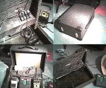
Anyway, I built my own pedal-board, and case for it, with a built in power strip (I'll post pics soon if anyones interested).

At first, I figured out a way to plug 4 or 5 wall warts into the power strip, but then I noticed that Boss was powering a bunch of pedals off of one adapter with the TU-5 (or whatever)
Well no way was I going to buy that thing, I mean how hard could it be to power those pedals, right? So I started tinkering around with my soldering iron. . .

Uh-Oh the pedal police are knocking on my door, gotta go for now.
 
I would love to see your pics. I have all kinds of problems with power supplies for my pedals and was thinking of trying the same type of thing.
 
I'm currently using as many as 7 stomp boxes. I'd love more info about this. I'm still buying 9 volts by the dozzen.
 
Being a tinkerer myself, I got rid of 9 volts and wall warts altogether. 9 volts batteries are unreliable, wall warts generate a poor quality DC voltage. They do not regulate their output so if you could look at the output on a scope, you would not see a flat line at 9 VDC but a train of positive half waves.

If you know how to use a soldering iron, you basically need a few components like a small transformer, a rectifier and 9 VDC regulators to build a true 9 VDC power supply. The toughest part really was to solder the different cables needed to connect different pedals. Some are 1/8 inch male, others female and they are always small, a little harder to solder.
 
chigbl, I'd like some more info on how to regulate the voltage, and get cleaner power, so more details, part numbers etc. about how you did that part of it.

The toughest part really was to solder the different cables needed to connect different pedals. Some are 1/8 inch male, others female and they are always small, a little harder to solder.

This part was the easiest, actually.

I'm always picking up wall warts every time I pass a garage sale, for the wires, if for nothing else.

So I got one of those speaker hook up blocks, with 4 red and 4 black push and release thingys (do I sound wee todd it?) like what's on the back of stereos and some boom boxes. You know, you push in the tab, and it opens up so you can put the speaker wire in, then you let go and it locks it in? Sorry, I'm blanking on what those are called.

So I soldered jumpers accross all the black together, and all the red together, in the back of it, then soldered the + & - leads of a 9v dc 800ma wall wart to the back as well.

Then I hooked this all into the underside of my pedalboard (I built it with an underside "compartment".) so that I could hook short cords into the jacks, and run them up through holes in the board directly to the pedals.

What is also cool about this setup, is you can reverse the polarity very easily for each pedal as needed. And you can hook more than one wire into each set of two also, so you're not limited to how many pedals you can power.

Problems: certain pedals seem to not like sharing power with others, especially Boss pedals. Not that they don't work, just adds a hum to the whole signal chain. But it's hit and miss , mostly it works great, the pedals that hum, I just use a separate wall wart in back of my power strip, there's plenty of room now.
That is why I want to learn about how to get cleaner power.

Well I'd like to get this post up, so I'll add more later.
 
You are a clever guy, Maestro. In my case, I put the electronics in a metal enclosure inside my wooden pedal board. Don't laugh at me, it was meant to be a prototype! Anyway, I decided to install a bunch of 1/8" jack sockets on this enclosure and then solder short extension cables with a 1/8" jack plug at one end and something fitting each pedal at the other end. So it was a lot of soldering and the soldering iron I used then was far from great.

But the most important is the regulated voltage and I will look into it ( it's been a while ) and let you know the parts I used and how they interconnect.
 
chigbl said:
If you know how to use a soldering iron, you basically need a few components like a small transformer, a rectifier and 9 VDC regulators to build a true 9 VDC power supply.

Could you plz give some details ?? I'm sure there's a lot of folks around here very interested !!!

This would be like a furman power cond for 9V pedals !!

TIA,
Herwig
 
I may start by a list of required parts; if there is an interest after that , I may later draw a complete diagram.
Ok so starting from the 120 VAC side going towards the desired 9 VDC.

Rectifier and filtering stage:

- 1 x 120 VAC toggle switch, optional.
- 1 x 120 VAC to 12.6 V, 3 Amps tranformer. RS 273-1511
- 4 x 1N5400 diodes. RS 276-1141
- 1 x 1000 uF electrolytic capacitor. RS 272-1019
- 2 X 5-lug tie points terminal strip. RS 274-688

Regulating:

- 1 x adjustable voltage regulator. RS 276-1778
- 1 x 240 ohms resistor.
- 1 x 5 Kohms potentiometer.
- 1 x universal PC board. RS ???

In my case, I have doubled the regulating part since the transfo. is rated at 3 amp and the regulator at 1.5 amp. I have mounted the bridge rectifier diodes and capacitor on the terminal strips and the dual regulator circuits on the PC board. This last one fits on a piece 2" by 1.5". The whole thing fits in a 5.0 x 4.5 x 2.5 inches metal enclosure.

This is indeed a pretty simple project and it could be completed with another supplier than RadioShack but I used what was available in my little town up north.

So as I said before, let me know if you want more info. and I will see what I can do for you guys.

CAUTION: Due to the presence of 120 VAC in this project, I ... blablabla ... not responsible ... blabla ... death ... and so on.
 
You're way too smart for me chigbl, I'm a tinkerer, not an electronic technician.

That said, I'm up to the challenge.

Can you tell me a book that'll get me up and running on terms, diagrams, and the basics of how to put stuff together. Like "Electronic Engineering for Dummies" or something?

I've truly just never gotten around to aquiring this knowledge before!
 
Also I'm working on getting some pics of the pedalboard and case up. Should have it by tommorow.


BTW, I'm not really that clever, just extremeley CHEAP!
 
Jeez, I am an electrical engineer. Maybe this is a product I can design and market. I see a power supply to power up to 10 pedals with interchangable ends to satisfy any size recepticle. Just an idea
 
Here's a view of the underside(top left) showing where the adapter wires plug in. The whole pedalboard is three pieces, a bottom "tray", a "cover" and the pedal board itself, which nests inside the "tray".

When I first built it, I was not thinking very big, so it's not as self contained for my current set up as I would ultimately like, but I don't really move it very often, so I'm in no hurry to build a new one right now.

top right is a view of the whole thing ready for transport. It's all plywood, with latches from Home Depot, corners and handle from Mac's Electronics, and Carpet from the local car stereo shop.

Bottom right is a larger view of the underside of the pedalboard showing the adapter jack and wires running up to the underside of the board, and the "tray" which the board always sits in.

Bottom left is everything hooked up. Please don't laugh at my pedals, I told you I was cheap. On the top left is a box I made which is 1-TRS to 2-1/4" mono outs. This is so I can run my pedals through my amps effect loop. It works great, and right now I have ZERO HUM (from the pedals anyway) What you can't see is the Midi controller pedal, or the Morley (i know it sucks) wah. So there are currently only 3 things on the one wall wart, the Zoom508 needed it's own power, and the Real Tube has a 3 prong plug.
 

Attachments

  • board comp med.jpg
    board comp med.jpg
    48.8 KB · Views: 72
Acorec, as an engineer, you probably noticed that my power supply is overdesigned. If you look at the Furman SPB-8 at http://www.furmansound.com/pro/pdlbrd/pdlbrd1.htm , they guarantee 100 mA per outlet for a total of 1 Amp. This means that I could power 30 pedals at the same time with my design. I do not remember having more than 4 or 5 pedals at the same time.

I now remember that I started from a variable power supply I had made for hobbying and later converted it to a 9VDC (but still adjustable) PS.

So all this to say that it could be made cheaper by using a smaller transformer and not doubling the regulators. I would probably add a fuse ( protect the whole thing ) and replace the 4 diodes by 1 ready to use bridge rectifier.

It means that 8 electronic/electric parts could build you a good 9VDC regulated PS to power 10 to 15 pedals, depending on the transfo. used. It is a rather simple project. ( I am not counting hardware like power cable, enclosure, screws or whatever is needed to mount the circuit and distribute the power).
 
...I don't really dare to ask... but would you know how to read that circuit in European 240V ??

Many TIA,
Herwig
 
I am not sure to understand your question, DeadPoet, but if you mean convert the whole thing for 240 outlet, the main change is to find a transfo that accept 240 VAC on the input side, the output being the same. i.e. something around 12-15 VAC.

The other parts stay the same but I do not know about availibility in Belgium. I mean do you have Radio Shack stores or something like "La Cabane des Radios"?
 
chigbl said:
I am not sure to understand your question, DeadPoet, but if you mean convert the whole thing for 240 outlet, the main change is to find a transfo that accept 240 VAC on the input side, the output being the same. i.e. something around 12-15 VAC.

The other parts stay the same but I do not know about availibility in Belgium. I mean do you have Radio Shack stores or something like "La Cabane des Radios"?

LOL! We used to have Radio Shack, but they basically left Europe.. AFAIK there is only one store left in Belgium, but I know a few electronic parts shops and a good electrician, he'll know what to do with the parts.

Many thanks anyway for the info, I'll try to build one (or let it be build for me ;) )


Herwig (living in the home of the Brussels wafers, Belgian chocolates and French fries ;) )

side note: it seems that most of the world thinks Belgium is an all French-speaking country (hence the name French fries btw), but actually a little over 50% is dutch speaking and there's about 5-10% German-speaking people here... difficult sometimes, but we manage :p
 
Back
Top